Installation Manual
26 Internal devices
4.10 The SmartLetUSee/LCD and SmartLetUSee/LED Repeater panels
The SmartLoop fire control panel supports 8 SmartLetUSee/LCD remote Repeater panels. These
remote panels can be connected to the RS485 bus on the motherboard by means of a 4-pole cable.
The EOL jumper must be set in the End of Line position on the last Repeater connected to the BUS.
Each Repeater must be assigned an address by means of the on-board DIP switches. Repeater panels
replicate all the SmartLoop fire system data and allow authorized personnel to access and control the
system in accordance with access authorization (access requires code entry). Each SmartLetUSee/
LCD module accommodates one SmartLetUSee/LED module that provides 48 status LEDs associated
with the zones. The ON/OFF logic of the LEDs can be defined separately for each Repeater during the
programming phase.
NOTE The SmartLetUSee/LED module can be used only in combination with a SmartLetUSee/LCD
module.
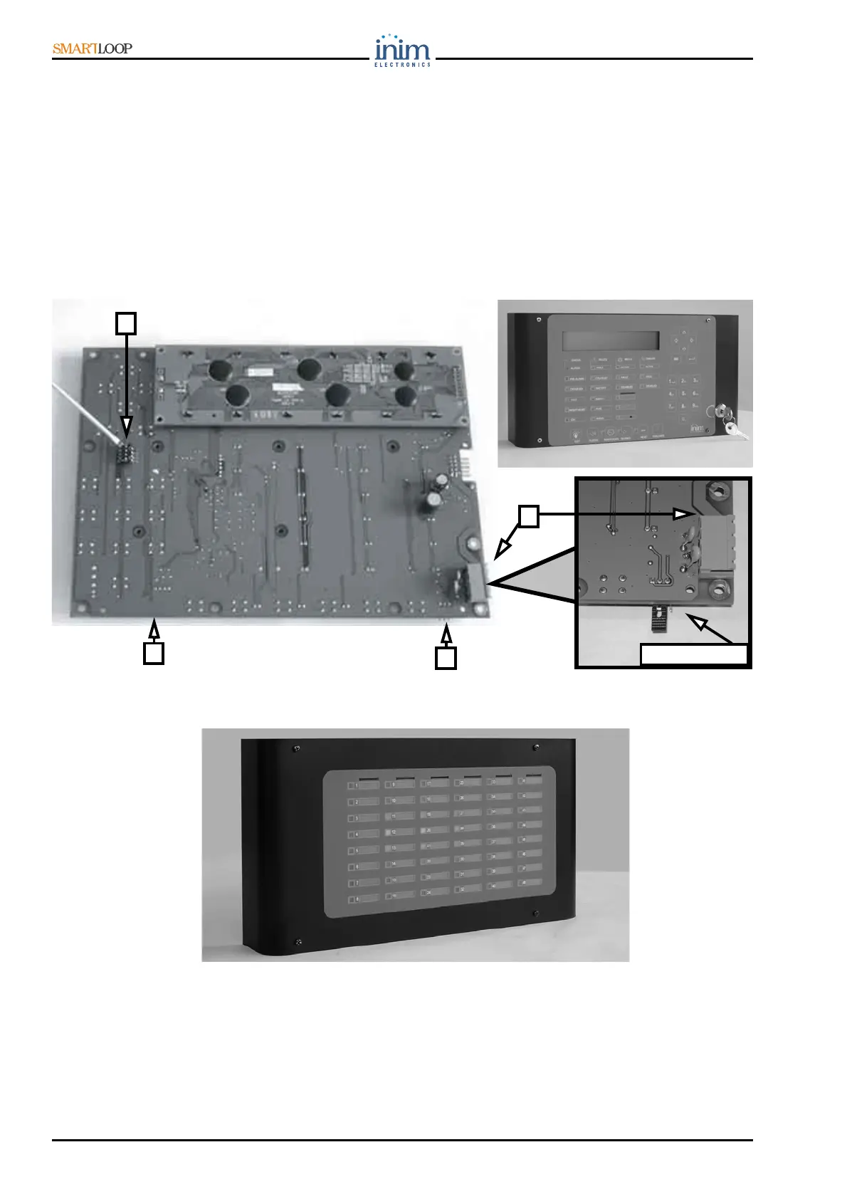
Figure 21 - The SmartLetUSee/LCD module
Figure 22 - The SmartLetUSee/LED module
4.10.1 The SmartLetUSee/LCD module components
1. Terminals for Repeater connections to the RS485 BUS
2. EOL jumper (2 positions) to be placed in End Of Line position on the last Repeater
3. SmartLetUSee/LED board connector
4. DIP switch strip for address assignment to the Repeater
4
1
3
2
2; EOL position