EasyManuals Logo
Home>INIM Electronics>Control Panel>SmartLoop

INIM Electronics SmartLoop Installation Manual

INIM Electronics SmartLoop
60 pages
To Next Page IconTo Next Page
To Previous Page IconTo Previous Page
Page #25 background imageLoading...
Page #25 background image
Installation Manual
Internal devices 25
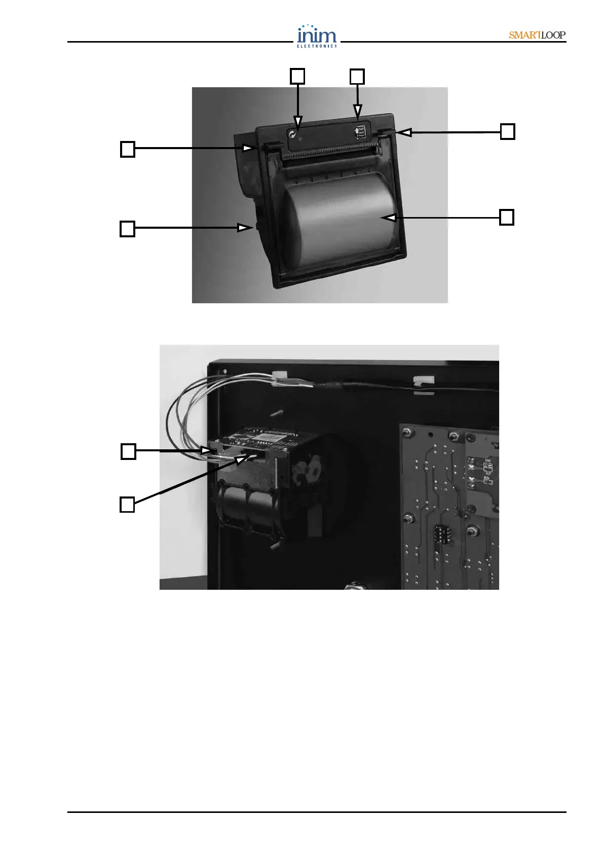
Figure 19 - The SmartLoop/PRN module
Figure 20 - The SmartLoop/PRN (Printer) module location on the motherboard
4.9.1 The SmartLoop/PRN module components
1. Power supply terminals (24V DC) to be connected to the red and black wires of the cable
(included)
2. Module to motherboard connector (for the cable jack)
3. Sliding locks
4. Printer module status LED
5. Paper roll button
6. Front-locking tabs
7. Paper slot
6
3
5
6
4
5
1
2

Table of Contents

Other manuals for INIM Electronics SmartLoop

Questions and Answers:

Question and Answer IconNeed help?

Do you have a question about the INIM Electronics SmartLoop and is the answer not in the manual?

INIM Electronics SmartLoop Specifications

General IconGeneral
BrandINIM Electronics
ModelSmartLoop
CategoryControl Panel
LanguageEnglish

Related product manuals