- 29 -
2 System Commissioning
2
2. F-1: command input of the running oor
After you enter the F1 menu, the 7-segment LEDs display the bottom oor (F6-01). You can press the
UP button to set the destination oor within the range of lowest to top and then press the SET button
to save the setting. The elevator runs to the destination oor, and the display switches over to the F0
menu at the same time.
3. F-2: fault reset and fault code display
After you enter the F-2 menu, the 7-segment LEDs display “0”. You can press the UP button to
change the setting to 1 or 2.
Display “1”: If you select this value and press the SET button, the system fault is reset. Then, the dis-
play automatically switches over to the F0 menu.
Display “2”: If you select this value and press the SET button, the 7-segment LEDs display the 11 fault
codes and occurrence time circularly. You can press the PRG button to exit.
4. F-3: time display
After you enter the F-3 menu, the 7-segment LEDs display the current system time circularly.
5. F-4: contract number display
After you enter the F-4 menu, the 7-segment LEDs display the user’s contract number.
6. F-5: running times display
After you enter the F-5 menu, the 7-segment LEDs display the elevator running times circularly.
7. F-6: door open/close control
After you enter the F6 menu, the 7-segment LEDs display “1-1”, and the UP and SET buttons respec-
tively stand for the door open button and door close button. You can press the PRG button to exit.
8. F-7: shaft auto-tuning command input
After you enter the F-7 menu, the 7-segment LEDs display “0”. You can select 0 or 1 here, where “1”
indicates the shaft auto-tuning command available.
After you select “1” and press the SET button, shaft auto-tuning is implemented if the conditions are
met. Meanwhile, the display switches over to the F0 menu. After shaft auto-tuning is complete, F-7 is
back to “0” automatically. If shaft auto-tuning conditions are not met, fault code “E35” is displayed.
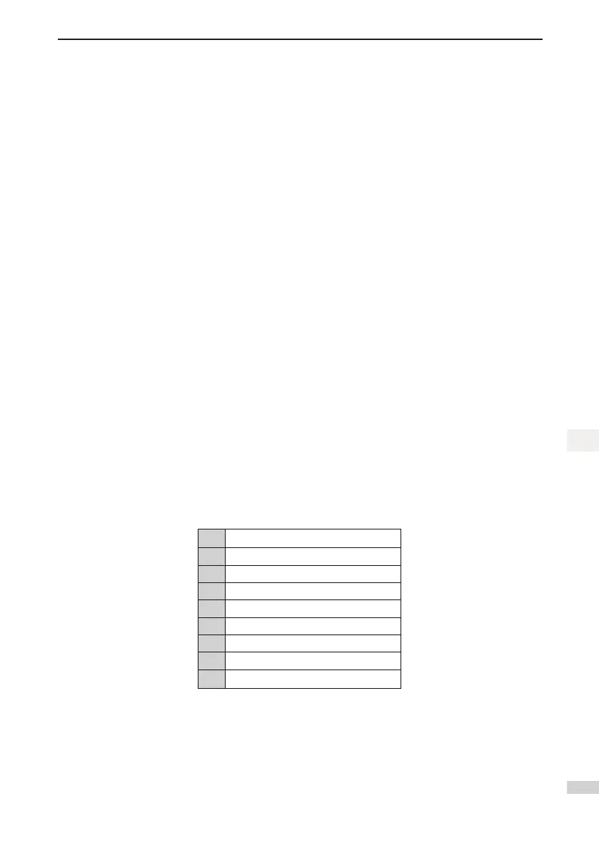
9. F-8: test function
After you enter the F-8 menu, the 7-segment LEDs display “0”. The setting of F-8 is described as fol-
lows:
1 Hall call forbidden
2 Door open forbidden
3 Overload forbidden
4 Limit switches disabled
6 Entering slip experiment state
7 UCMP manual detection
8 Manual detection of braking force
9 Balance coefcient detection
10 Slip amount test
The procedure of balance coefcient detection is as follows:
Step 1. Set F-8 to 9. The HCB at hall displays “
⊙
”, and the keypad automatically displays the last
balance coefcient “XXP” (“P” indicates percentage). The elevator automatically runs to the bottom
oor and opens the door, and the keypad displays “0.0P” in blinking state. Put a weight inside the car,
and manually enter the load (for example, 40.0, indicating 40.0%).
Step 2. Hold down SET; the keypad displays the oor number, and the system starts to detect the bal-
ance coefcient. The elevator automatically runs to the top oor and then back to the bottom oor; “OP”
 Loading...