Intel® 3210 and 3200 Chipset Thermal/Mechanical Design Guide 13
Packaging Technology
2.1 Non-Critical to Function Solder Joints
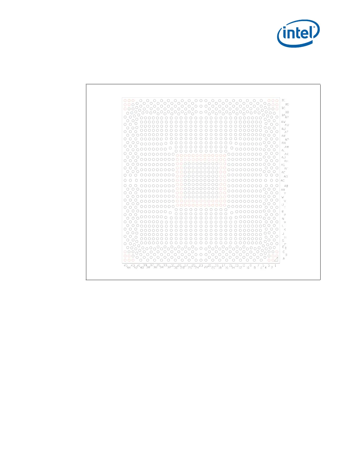
Intel has defined selected solder joints of the MCH as non-critical to function (NCTF)
when evaluating package solder joints post environmental testing. The MCH signals at
NCTF locations are typically redundant ground or no-critical reserved, so the loss of the
solder joint continuity at end of life conditions will not affect the overall product
functionality. Figure 2-4 identifies the NCTF solder joints of the MCH package.
2.2 Package Mechanical Requirements
The Intel
®
3210 and 3200 Chipset package has an Integrated Heat Spreader (IHS)
which is capable of sustaining a maximum static normal load of 15-lbf. This mechanical
maximum load limit should not be exceeded during heatsink assembly, shipping
conditions, or standard use conditions. Also, any mechanical system or component
testing should not exceed the maximum limit. The package substrate should not be
used as a mechanical reference or load-bearing surface for the thermal and mechanical
solution.
Notes:
1. These specifications apply to uniform compressive loading in a direction normal to
the package.
Figure 2-4. Non-Critical to Function Solder Joints