Intel® 3210 and 3200 Chipset Thermal/Mechanical Design Guide 29
Thermal Metrology
20.Attach the tip of the thermocouple to the solder block (perform this before turning
on the solder station switch) and connect to a Thermocouple meter to monitor the
temperature of the block. Refer to Figure 5-17.
21.Connect (Thermocouple being installed) to a second thermocouple meter to
monitor the IHS temperature and make sure this doesn’t exceed 155 °C at any
time during the process. Refer to Figure 5-17.
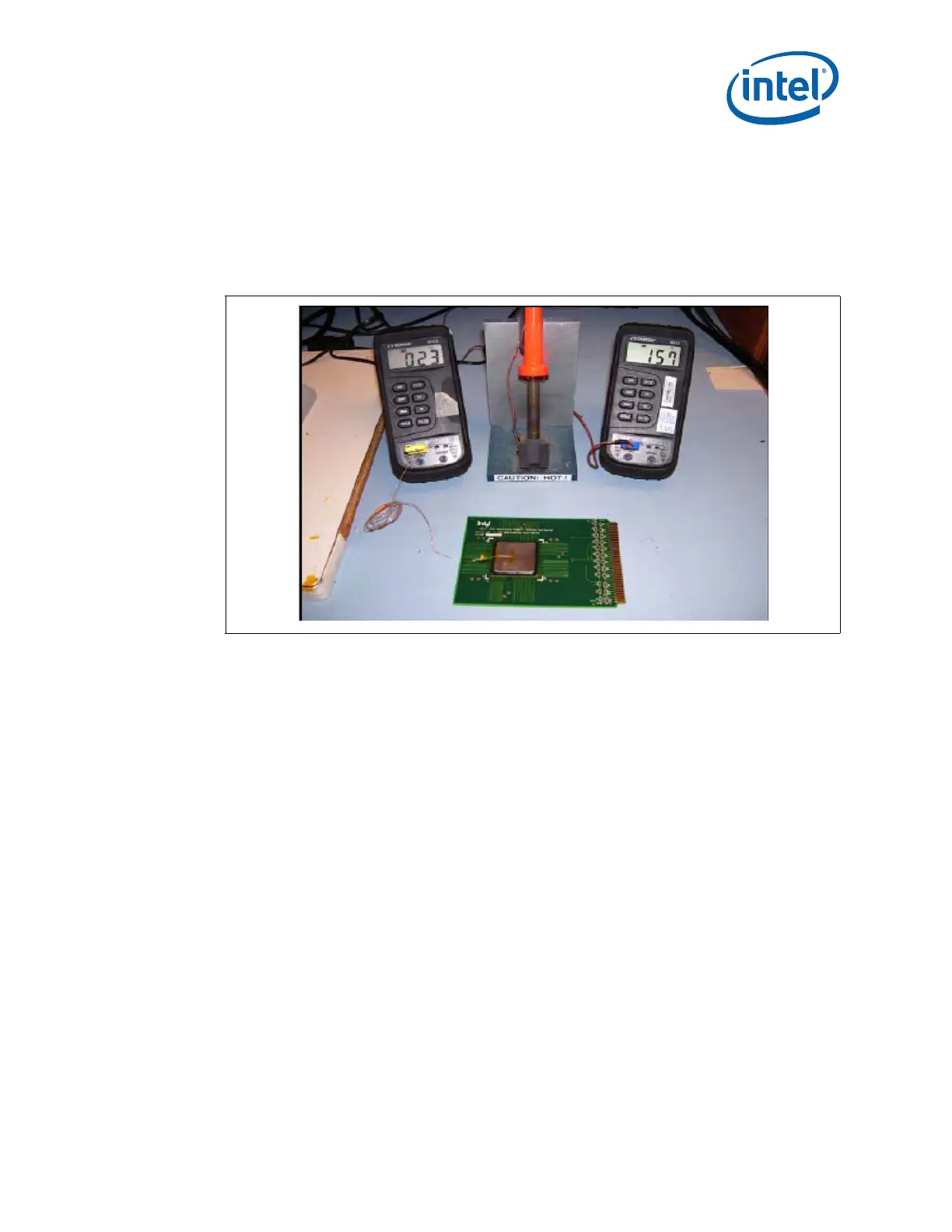
Note: Device in place; Two temperature monitoring meters; Heater block fixture. The heater block is currently
reading 157 °C and the Thermocouple inside IHS is reading 23 °C.
22.Place the solder fixture on the IHS device. Refer to Figure 5-18.
Figure 5-17. Solder Block Setup