Introduction
8 Intel® 3210 and 3200 Chipset Thermal/Mechanical Design Guide
1.1 Design Flow
1.2 Definition of Terms
FC-BGA Flip Chip Ball Grid Array. A package type defined by a plastic
substrate where a die is mounted using an underfill C4
(Controlled Collapse Chip Connection) attach style. The primary
electrical interface is an array of solder balls attached to the
substrate opposite the die. Note that the device arrives at the
customer with solder balls attached.
BLT Bond line thickness. Final settled thickness of the thermal
interface material after installation of heatsink.
MCH Memory controller hub. The chipset component contains the
processor interface, the memory interface, the PCI Express*
interface and the DMI interface.
ICH I/O controller hub. The chipset component contains the MCH
interface, the SATA interface, the USB interface, the IDE
interface, the LPC interface, and so forth.
IHS Integrated Heat Spreader. A thermally conductive lid integrated
into the package to improve heat transfer to a thermal solution
through heat spreading.
T
case_max
Maximum die or IHS temperature allowed. This temperature is
measured at the geometric center of the top of the package die
or IHS.
T
case_min
Minimum die or IHS temperature allowed. This temperature is
measured at the geometric center of the top of the package die
or IHS.
TDP Thermal design power. Thermal solutions should be designed to
dissipate this target power level. TDP is not the maximum power
that the chipset can dissipate.
TIM Thermal Interface Material. Thermally conductive material
installed between two surfaces to improve heat transfer and
reduce interface contact resistance.
T
LA
The local ambient air temperature at the component of interest.
The local ambient temperature should be measured just
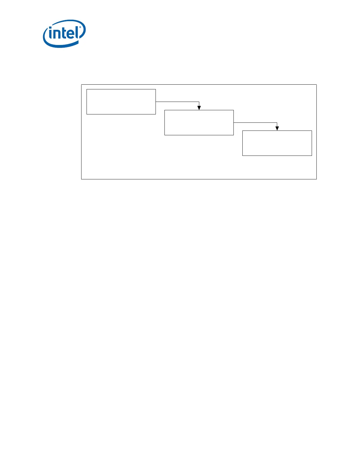
Figure 1-1. Thermal Design Process
y Thermal Model
y Thermal Model User's Guide
Step 1: Thermal
Simulation
y Thermal Reference
y Mechanical Reference
Step 2: Heatsink Selection
y Thermal Testing Software
y Software User's Guide
Step 3: Thermal Validation
001239