Thermal Metrology
24 Intel® 3210 and 3200 Chipset Thermal/Mechanical Design Guide
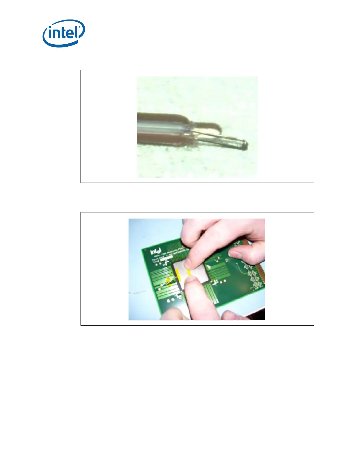
8. Bend the wire at the edge of the IHS groove and secure it in place using Kapton*
tape. Refer to Figure 5-8.
9. Verify under the microscope that the Thermocouple bead is still slightly bent, if not,
use a fine point tweezers to put a slight bend on the tip. The purpose of this step is
to ensure that the Thermocouple tip is in contact with the bottom of groove. Refer
to Figure 5-9.
Figure 5-7. Extending Slightly the Exposed Wire over the End of Groove
Figure 5-8. Securing Thermocouple Wire with Kapton* Tape Prior to Attach