Packaging Technology
14 Intel® 3210 and 3200 Chipset Thermal/Mechanical Design Guide
2. This is the maximum force that can be applied by a heatsink retention clip. The clip
must also provide the minimum specified load of 7.6 lbf on the package to ensure
TIM performance assuming even distribution of the load.
3. These specifications are based on limited testing for design characterization.
Loading limits are for the package only.
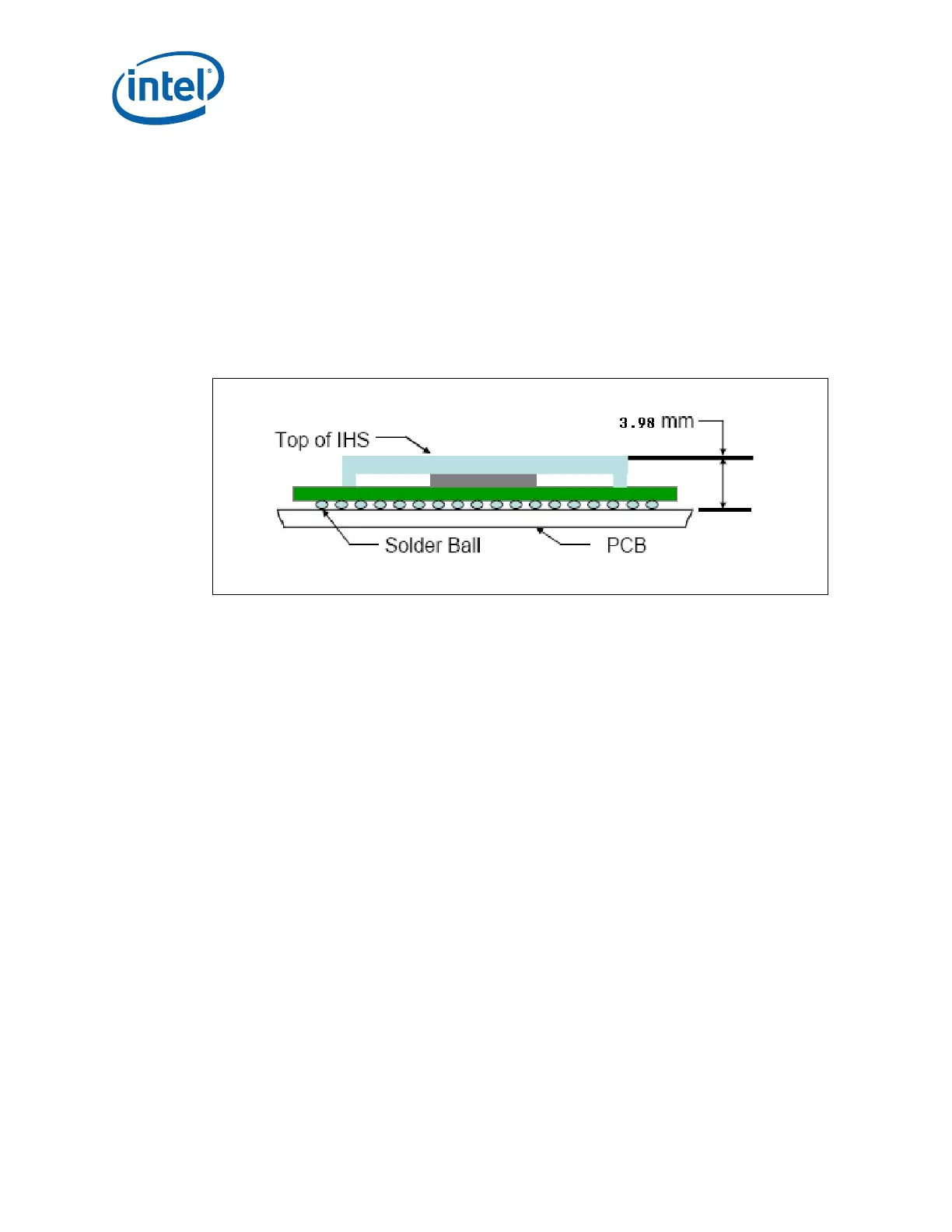
To ensure that the package static load limit is not exceeded, the designer should
understand the post reflow package height shown in Figure 2-5. The following figure
shows the nominal post-reflow package height assumed for calculation of a heatsink
clip preload of the reference design. Please refer to the package drawing in Figure 2-1
to perform a detailed analysis.
§
Figure 2-5. Package Height