Thermal Metrology
26 Intel® 3210 and 3200 Chipset Thermal/Mechanical Design Guide
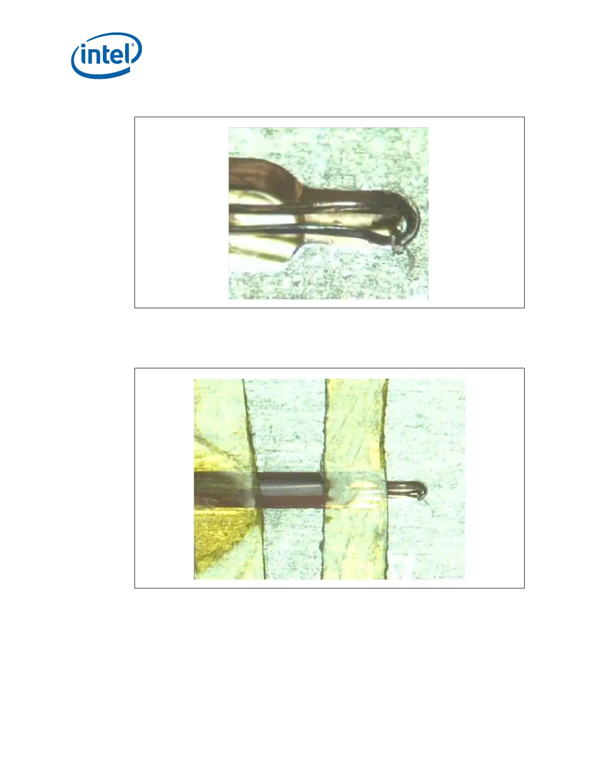
13.Place a second small piece of Kapton* tape on top of the IHS where it narrows at
the tip. This tape will create a solder dam and keep solder from flowing down the
IHS groove during the melting process. Refer to Figure 5-12.
14.Measure resistance from the Thermocouple connector (hold both wires to a DMM
probe) to the IHS surface, this should display the same value as read during
Thermocouple conditioning Section 5.1.4.1 step 3. This step insures the bead is still
making good contact to the IHS. Refer to Figure 5-13.
Figure 5-11. Placing Thermocouple Bead into the Bottom of the Groove
Figure 5-12. Second Tape Installation