Thermal Metrology
28 Intel® 3210 and 3200 Chipset Thermal/Mechanical Design Guide
17.Place the two pieces of solder in parallel, directly over the thermocouple bead.
Refer to Figure 5-16.
18.Measure the resistance from the thermocouple end wires again using the DMM
(Refer to Section 5.1.4.1 step 3) to ensure that the bead is still properly contacting
the IHS.
5.1.4.3 Solder Process
19.Turn on the Solder Block station and heat it up to 170 °C±5 °C.
Note: The heater block temperature must be set at a greater temperature to ensure that the
solder on the IHS can reach 150 °C - 155 °C. Make sure to monitor the Thermocouple
meter when waiting for solder to flow. Damage to the package may occur if a
temperature of 155 °C is exceeded on the IHS.
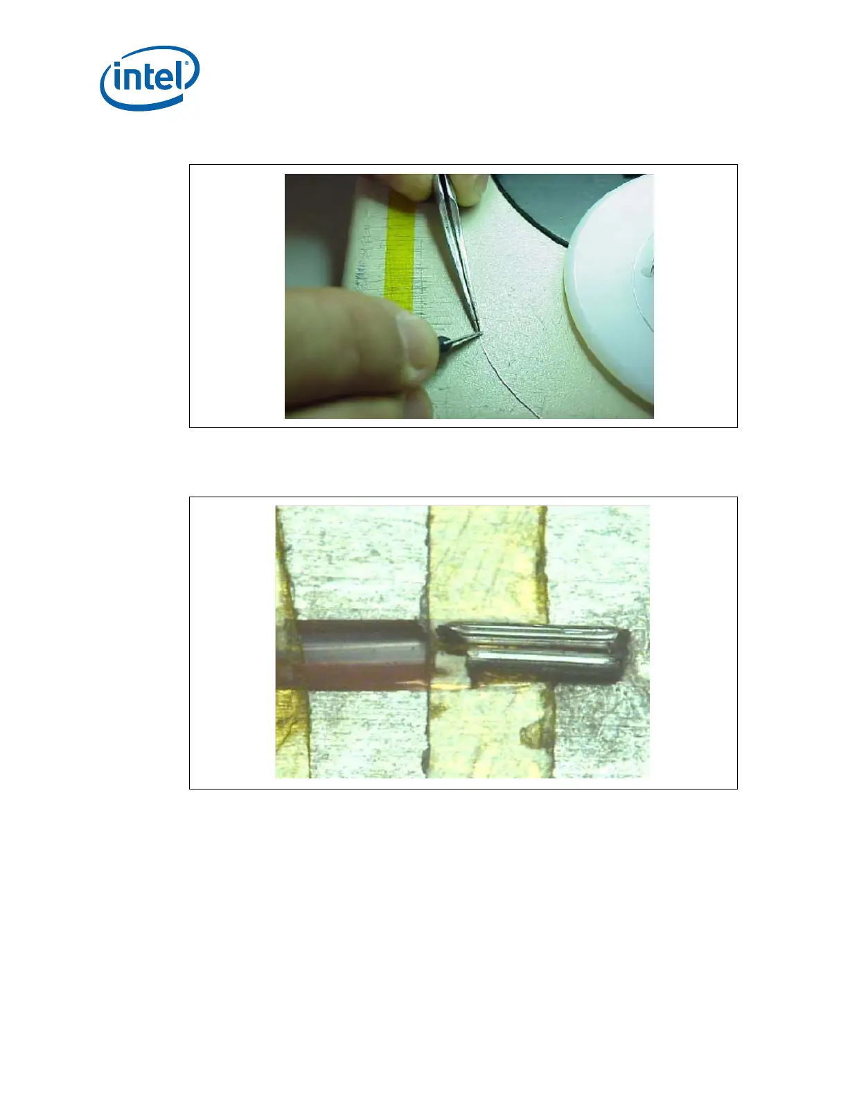
Figure 5-15. Cutting Solder
Figure 5-16. Positioning Solder on IHS