Thermal Metrology
22 Intel® 3210 and 3200 Chipset Thermal/Mechanical Design Guide
Select a machine shop that is capable of holding drawing-specified tolerances. IHS
groove geometry is critical for repeatable placement of the thermocouple bead,
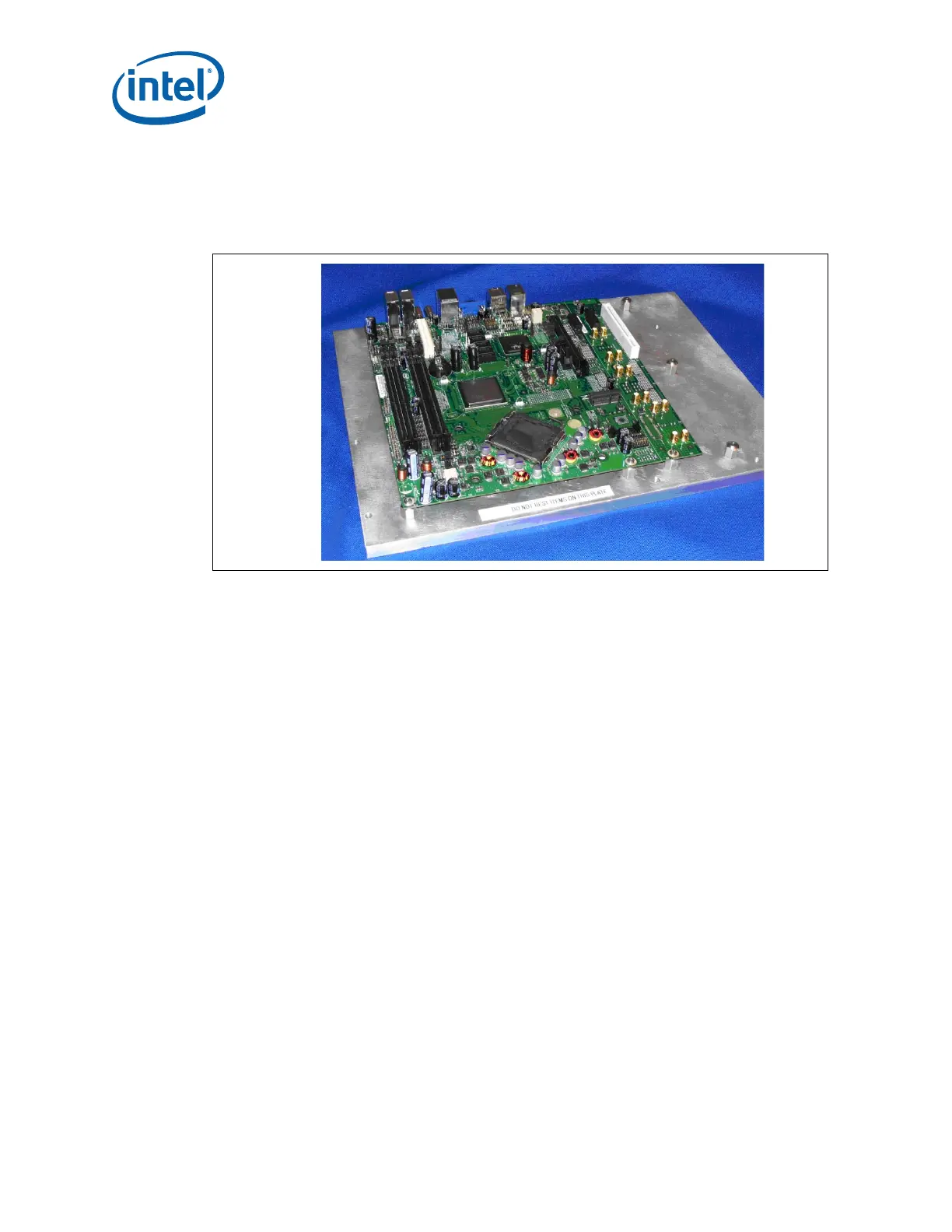
ensuring precise thermal measurements. A fixture plate should be used to machine the
IHS groove on the FCBGA7 Chipset Package on the Live Board. Refer to Figure 5-4.
5.1.4 Thermocouple Attach Procedure
In order to accomplish the thermocouple attach procedure, the following steps are
required:
1. Thermocouple conditioning and preparation
2. Thermocouple attach to the IHS
3. Soldering process
4. Cleaning and completion of the thermocouple installation
5.1.4.1 Thermocouple Conditioning and Preparation
1. Use a calibrated thermocouple, as specified in Section 5.1.3.
2. Under a microscope verify the thermocouple insulation meets the quality
requirements. The insulation should be about 1/16 inch (0.062 ± 0.030) from the
end of the bead. Refer to Figure 5-5.
Figure 5-4. The Live Board on the Fixture Plate