Reference Thermal Solution
36 Intel® 3210 and 3200 Chipset Thermal/Mechanical Design Guide
6.3 Mechanical Design Envelope
While each design may have unique mechanical volume and height restrictions or
implementation requirements, the height, width, and depth constrains typically placed
on the Intel
®
3210 and 3200 Chipset thermal solution are shown in Appendix B.
The location of hole patens and keepout zones for the reference thermal solution are
shown in Figure B-2 and Figure B-3.
6.4 Thermal Solution Assembly
The reference thermal solution for the Intel
®
3210 and 3200 Chipset is a passive
extruded heatsink with thermal interface. Figure 6-2 shows the reference thermal
solution assembly and associated components.
Full mechanical drawings of the thermal solution assembly and the heatsink are
provided in Appendix B.
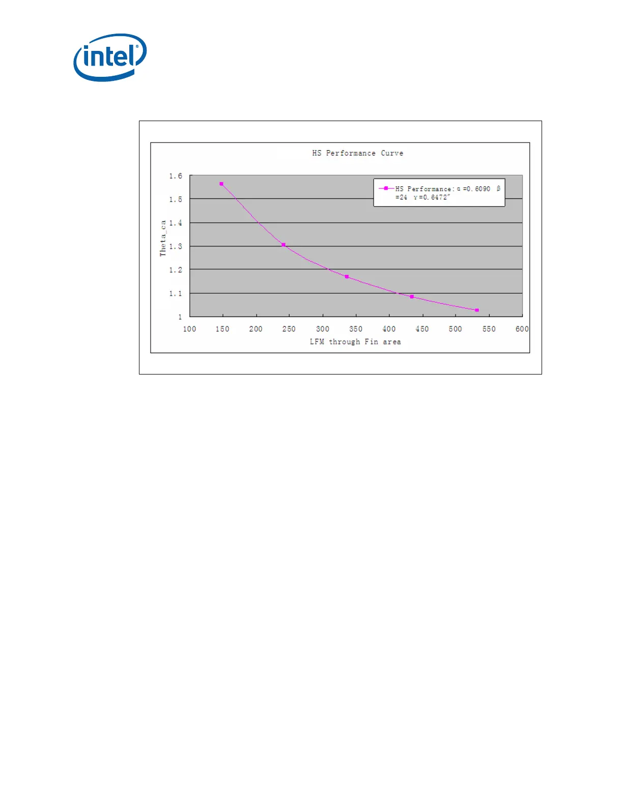
Figure 6-1. Reference Heatsink Measured Thermal Performance vs. Approach Velocity