Datasheet, Volume 1 31
Interfaces
2.4.2 Processor Graphics Display
The Processor Graphics controller display pipe can be broken down into three
components:
• Display Planes
• Display Pipes
• DisplayPort and Intel FDI
2.4.2.1 Display Planes
A display plane is a single displayed surface in memory and contains one image
(desktop, cursor, overlay). It is the portion of the display hardware logic that defines
the format and location of a rectangular region of memory that can be displayed on
display output device and delivers that data to a display pipe. This is clocked by the
Core Display Clock.
2.4.2.1.1 Planes A and B
Planes A and B are the main display planes and are associated with Pipes A and B
respectively. The two display pipes are independent, allowing for support of two
independent display streams. They are both double-buffered, which minimizes latency
and improves visual quality.
2.4.2.1.2 Sprite A and B
Sprite A and Sprite B are planes optimized for video decode, and are associated with
Planes A and B respectively. Sprite A and B are also double-buffered.
2.4.2.1.3 Cursors A and B
Cursors A and B are small, fixed-sized planes dedicated for mouse cursor acceleration,
and are associated with Planes A and B respectively. These planes support resolutions
up to 256 x 256 each.
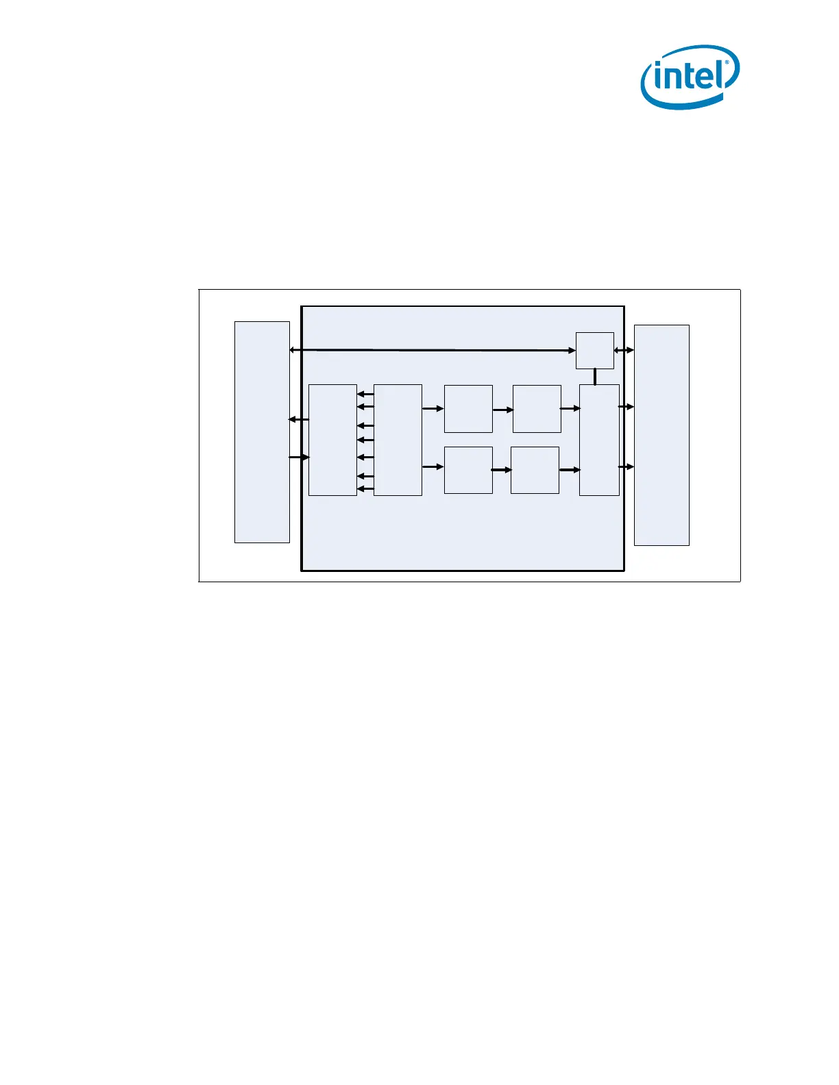
Figure 2-7. Processor Display Block Diagram
Memory Host Interface
(Outside of Display Engine)
Display
Arbiter
Display
Planes
& VGA
Display
Pipe A
Display
Pipe B
Display
Port
Control
A
Display
Port
Control
B
Intel
FDI
(Tx
Side)
DMI
PCH Display Engine