Package Mechanical and Storage Specifications
12 Thermal/Mechanical Specifications and Design Guidelines
2.1.1 Package Mechanical Drawing
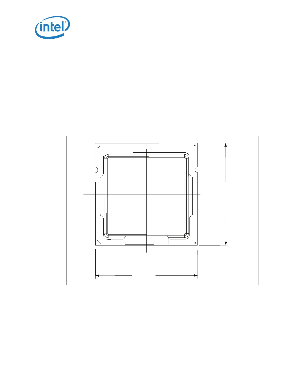
Figure 2-2 shows the basic package layout and dimensions. The detailed package
mechanical drawings are in Appendix D. The drawings include dimensions necessary to
design a thermal solution for the processor. These dimensions include:
1. Package reference dimensions with tolerances (total height, length, width, and so
forth.)
2. IHS parallelism and tilt
3. Land dimensions
4. Top-side and back-side component keep-out dimensions
5. Reference datums
6. All drawing dimensions are in mm
2.1.2 Processor Component Keep-Out Zones
The processor may contain components on the substrate that define component keep-
out zone requirements. A thermal and mechanical solution design must not intrude into
the required keep-out zones. Decoupling capacitors are typically mounted to either the
topside or land-side of the package substrate. See Figure B-3 and Figure B-4 for keep-
out zones. The location and quantity of package capacitors may change due to
manufacturing efficiencies but will remain within the component keep-in. This keep-in
zone includes solder paste and is a post reflow maximum height for the components.
Figure 2-2. Package View
37.5
37.5