Independent Loading Mechanism (ILM)
26 Thermal/Mechanical Specifications and Design Guidelines
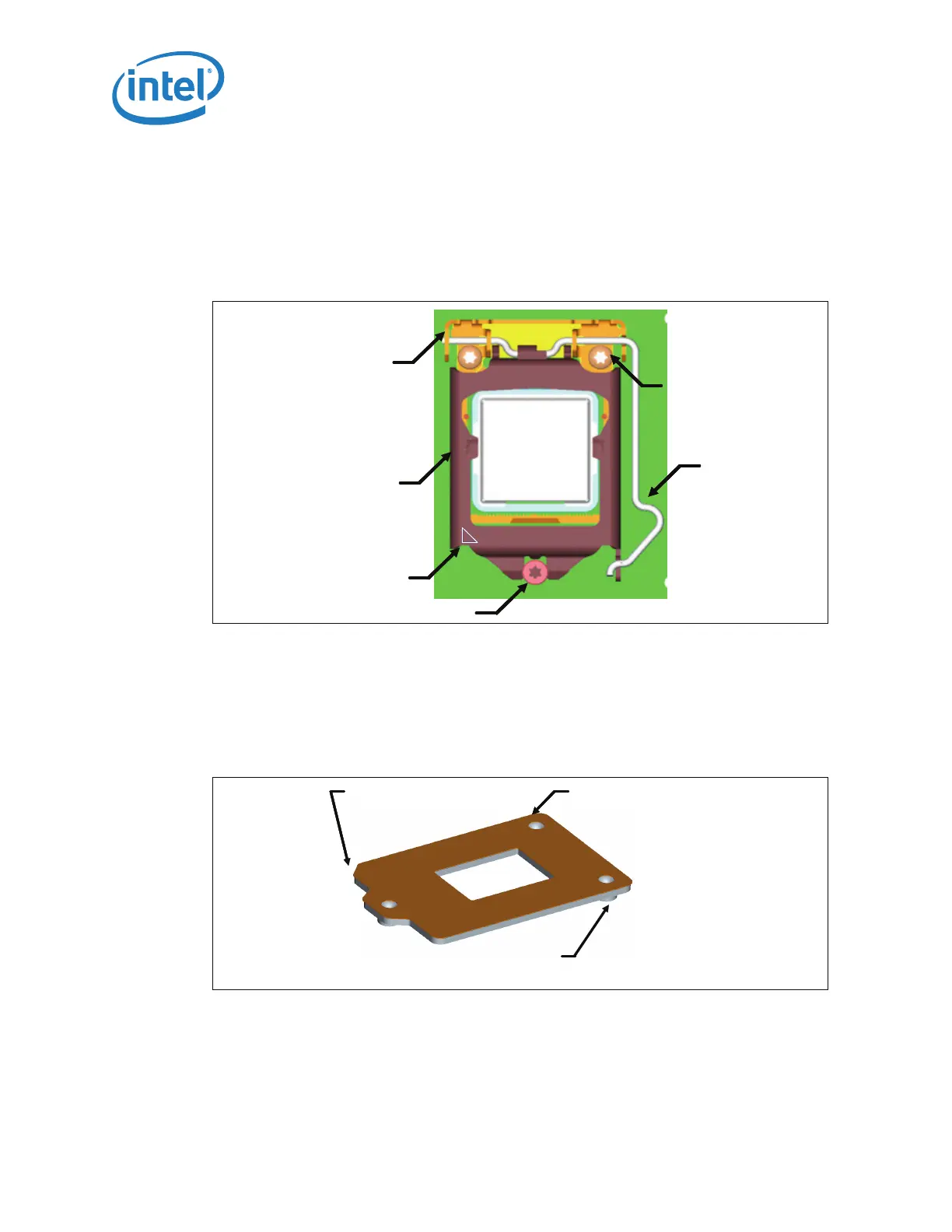
When closed, the load plate applies two point loads onto the IHS at the “dimpled”
features shown in Figure 4-1. The reaction force from closing the load plate is
transmitted to the hinge frame assembly and through the fasteners to the back plate.
Some of the load is passed through the socket body to the board inducing a slight
compression on the solder joints.
A pin 1 indicator will be marked on the ILM cover assembly.
4.1.2 ILM Back Plate Design Overview
The back plate (see Figure 4-2) is a flat steel back plate with pierced and extruded
features for ILM attach. A clearance hole is located at the center of the plate to allow
access to test points and backside capacitors if required. An insulator is pre-applied. A
notch is placed in one corner to assist in orienting the back plate during assembly.
Figure 4-1. ILM Cover Assembly
Fasteners
Load
Leve
Load
Plate
Hinge /
Frame
Assy
Shoulder Screw
Pin 1 Indicator
Fasteners
Load
Leve
Load
Plate
Hinge /
Frame
Assy
Shoulder Screw
Pin 1 Indicator
Figure 4-2. Back Plate
Die Cut
Insulator
Pierced & Extruded
Thread Features
Assembly
Orientation
Feature
Die Cut
Insulator
Pierced & Extruded
Thread Features
Assembly
Orientation
Feature