LGA1156 Socket
22 Thermal/Mechanical Specifications and Design Guidelines
3.4 Package Installation / Removal
As indicated in Figure 3-6, access is provided to facilitate manual installation and
removal of the package.
To assist in package orientation and alignment with the socket:
• The package Pin 1 triangle and the socket Pin1 chamfer provide visual reference for
proper orientation.
• The package substrate has orientation notches along two opposing edges of the
package, offset from the centerline. The socket has two corresponding orientation
posts to physically prevent mis-orientation of the package. These orientation
features also provide initial rough alignment of package to socket.
• The socket has alignment walls at the four corners to provide final alignment of the
package.
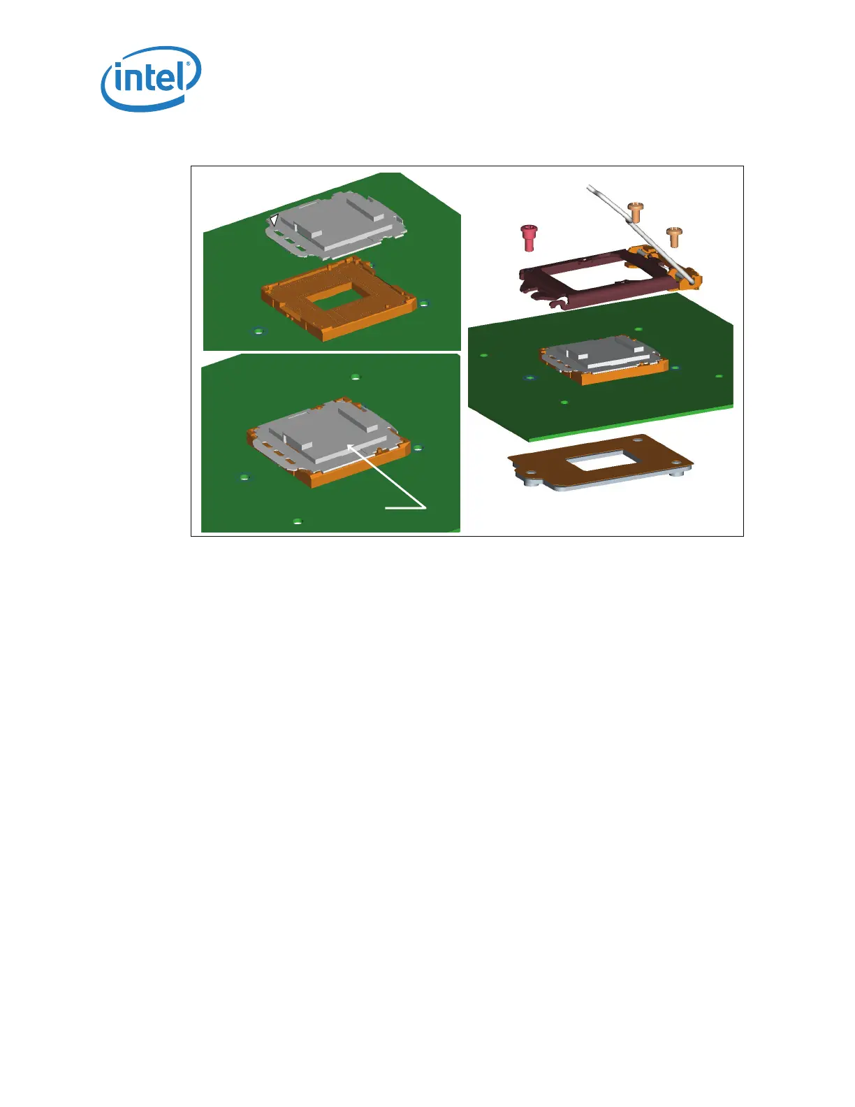
Figure 3-5. Pick and Place Cover
Pick & Place Cover
Pin 1
ILM Installation
Pick & Place Cover
Pin 1
ILM Installation