ATX Reference Thermal Solution
60 Thermal/Mechanical Specifications and Design Guidelines
8.2 Geometric Envelope for the Intel Reference ATX
Thermal Mechanical Design
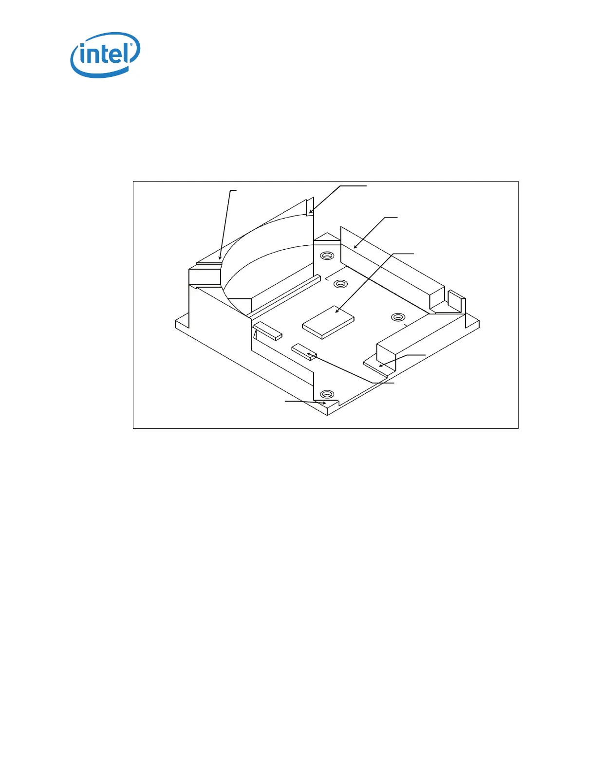
Figure 8-2 shows a 3-D representation of the board component keep out for the
reference ATX thermal solution. A fully dimensioned drawing of the keepout information
is available at Figure B-1 and Figure B-2 in Appendix B.
Note: All maximum component heights are post reflow or assembly.
Note: The maximum height of the reference thermal solution (in Figure 8-1) above the
motherboard is 46.00 mm [1.81 inches], and is compliant with the motherboard
primary side height constraints defined in the ATX Specification and the microATX
Motherboard Interface Specification found at http://www.formfactors.org.
The reference solution requires a chassis obstruction height of at least 81.30 mm
[3.20 inches], measured from the top of the motherboard. This allows for appropriate
fan inlet airflow to ensure fan performance, and therefore overall cooling solution
performance. This is compliant with the recommendations found in both ATX
Specification and microATX Motherboard Interface Specification documents.
8.3 Heatsink Mass and Center of Gravity
• Total mass including plastic fan housing and fasteners <500 g.
• Assembly center of gravity ≤25.4 mm, measured from the top of the IHS.
8.4 Thermal Interface Material
A thermal interface material (TIM) provides conductivity between the IHS and heat
sink. The designs use Dow Corning TC-1996. The TIM application is 0.14 g, which will
be a nominal 20 mm diameter (~0.79 inches).
§§
Figure 8-2. ATX KOZ 3-D Model Primary (Top) Side
27.00mm Maximum
Component Height
(3 places)
10.10mm Maximum
Component Height
(5 places)
2.07mm Maximum
Component Height
(1 place)
1.20mm Maximum
Component Height
(1 place)
2.50mm Maximum
Component Height
(6 places)
.
mm
ax
mum
Component Height
(3 places)
1.6 mm Maximum
Component Height
(2 places)
27.00mm Maximum
Component Height
(3 places)
10.10mm Maximum
Component Height
(5 places)
2.07mm Maximum
Component Height
(1 place)
1.20mm Maximum
Component Height
(1 place)
2.50mm Maximum
Component Height
(6 places)
.
mm
ax
mum
Component Height
(3 places)
1.6 mm Maximum
Component Height
(2 places)