Independent Loading Mechanism (ILM)
28 Thermal/Mechanical Specifications and Design Guidelines
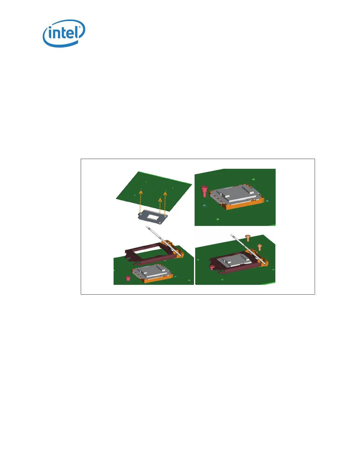
4.2 Assembly of ILM to a Motherboard
The ILM design allows a bottoms up assembly of the components to the board. See
Figure 4-4 for step by step assembly sequence.
1. Place the back plate in a fixture. The motherboard is aligned with the fixture.
2. Install the shoulder screw in the single hole near Pin 1 of the socket. Torque to a
minimum and recommended 8 inch-pounds, but not to exceed 10 inch-pounds.
3. Align and place the ILM cover assembly over the socket.
4. Install two (2) 6-32 fasteners. Torque to a minimum and recommended 8 inch-
pounds, but not to exceed 10 inch-pounds.
The thread length of the shoulder screw accommodates a nominal board thicknesses of
0.062”.
.
Figure 4-4. ILM Assembly
Step 1 Step 2
Step 3
Step 4
Step 1 Step 2
Step 3
Step 4
Step 1 Step 2
Step 3
Step 4