Thermal/Mechanical Specifications and Design Guidelines 69
Boxed Processor Specifications
10.4 Thermal Specifications
This section describes the cooling requirements of the fan heatsink solution used by the
boxed processor.
10.4.1 Boxed Processor Cooling Requirements
The boxed processor may be directly cooled with a fan heatsink. However, meeting the
processor's temperature specification is also a function of the thermal design of the
entire system, and ultimately the responsibility of the system integrator. The processor
temperature specification is found in Chapter 6 of this document. The boxed processor
fan heatsink is able to keep the processor temperature within the specifications (see
Ta b l e 6.1) in chassis that provide good thermal management. For the boxed processor
fan heatsink to operate properly, it is critical that the airflow provided to the fan
heatsink is unimpeded. Airflow of the fan heatsink is into the center and out of the
sides of the fan heatsink. Airspace is required around the fan to ensure that the airflow
through the fan heatsink is not blocked. Blocking the airflow to the fan heatsink
reduces the cooling efficiency and decreases fan life. Figure 10-7 and Figure 10-8
illustrate an acceptable airspace clearance for the fan heatsink. The air temperature
entering the fan should be kept below 40 ºC. Again, meeting the processor's
temperature specification is the responsibility of the system integrator.
Table 10-1. Fan Heatsink Power and Signal Specifications
Description Min Typ Max Unit Notes
+12 V: 12 volt fan power supply 11.4 12.0 12.6 V —
IC:
• Maximum fan steady-state current draw
• Average steady-state fan current draw
• Maximum fan start-up current draw
• Fan start-up current draw maximum duration
—
—
—
—
1.2
0.5
2.2
1.0
—
—
—
—
A
A
A
Second
—
SENSE: SENSE frequency — 2 — pulses per fan
revolution
1
NOTES:
1. Baseboard should pull this pin up to 5 V with a resistor.
CONTROL 21 25 28 kHz
2, 3
2. Open drain type, pulse width modulated.
3. Fan will have pull-up resistor for this signal to maximum of 5.25 V.
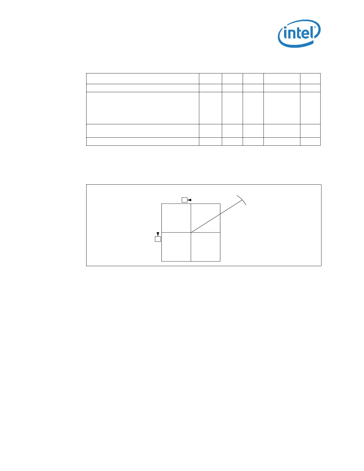
Figure 10-6. Baseboard Power Header Placement Relative to Processor Socket
B
C
R110
[4.33]