Thermal/Mechanical Specifications and Design Guidelines 15
Package Mechanical and Storage Specifications
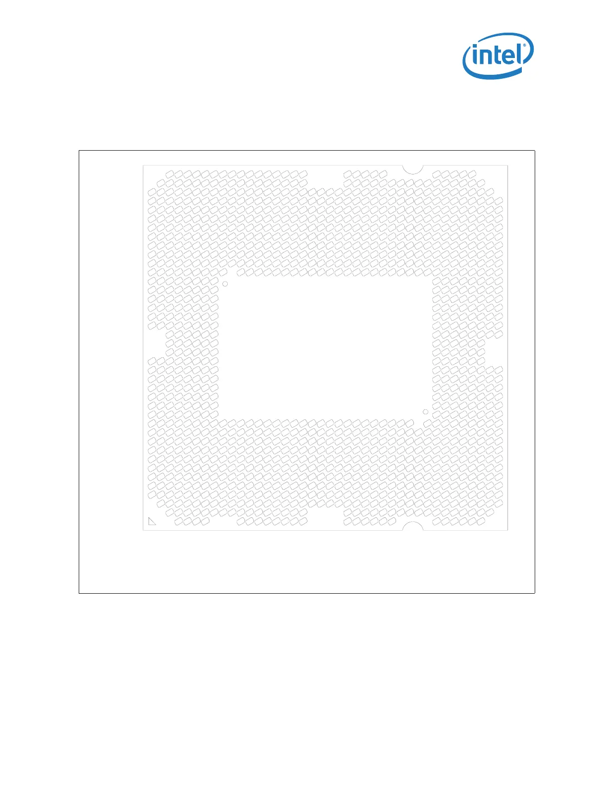
2.1.9 Processor Land Coordinates
Figure 2-4 shows the bottom view of the processor package.
.
Figure 2-4. Processor Package Lands Coordinates
AY
AV
AT
AP
AM
AK
AH
AF
AD
AB
Y
V
T
P
M
K
H
F
D
B
AW
AU
AR
AN
AL
AJ
AG
AE
AC
AA
W
U
N
R
K
J
G
E
C
A
1 3 5 7 9 11 13 15 17 19 21 23 25 27 29 31
33 35 37 39
2 4 6 8 10 12 14 16 18 20 22 24 26 28 30 32
34 36 38 40