Error Messages and Beep Codes
125
Table 86. Beep Codes
Beep Description
1 Refresh failure
2 Parity cannot be reset
3 First 64 KB memory failure
4 Timer not operational
5 Not used
6 8042 GateA20 cannot be toggled
7 Exception interrupt error
8 Display memory R/W error
9 Not used
10 CMOS Shutdown register test error
11 Invalid BIOS (e.g. POST module not found, etc.)
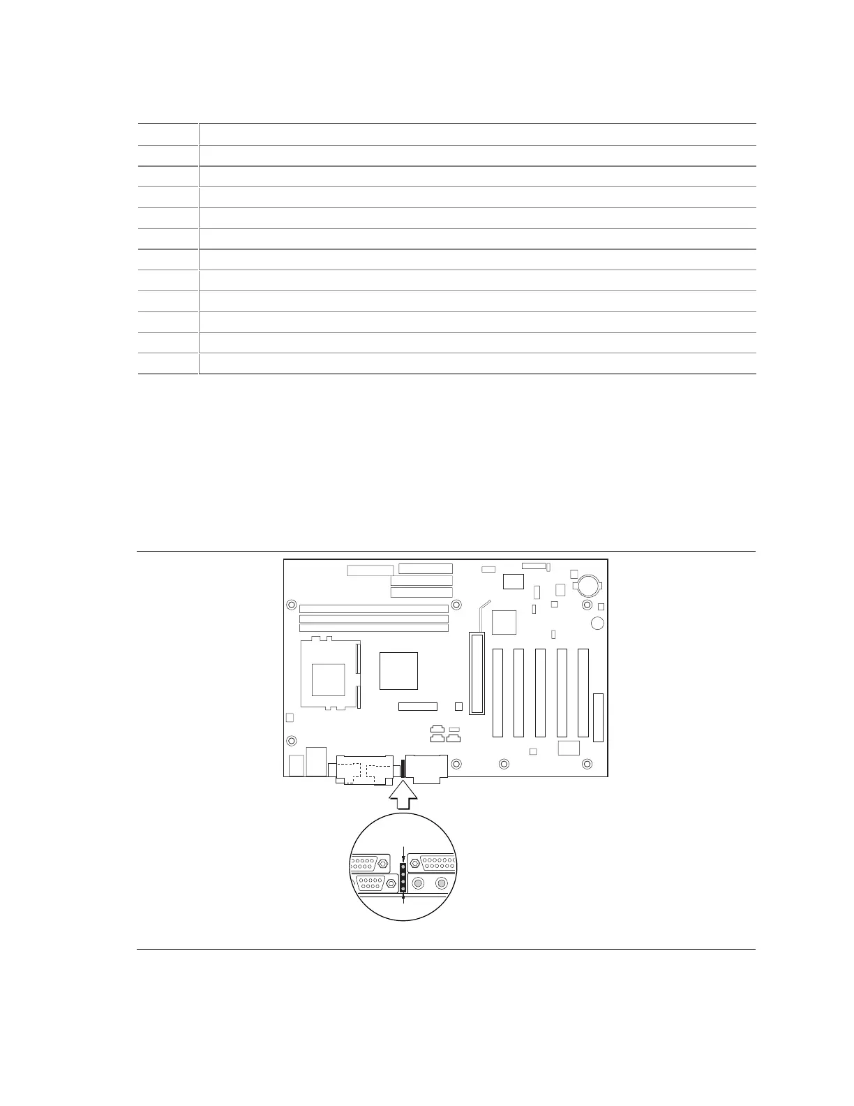
5.6 Diagnostic LEDs
The enhanced diagnostics feature consists of a hardware decoder and four LEDs located between the
audio connectors and the serial port connector on the back panel. This feature requires no modifications
to the chassis (other than I/O back panel shield) or cabling.
Figure 17 shows the location of the diagnostic LEDs. Table 87 lists the diagnostic codes displayed by
the LEDs.
OM10051
1
4
Figure 17. Diagnostic LEDs