Technical Reference
59
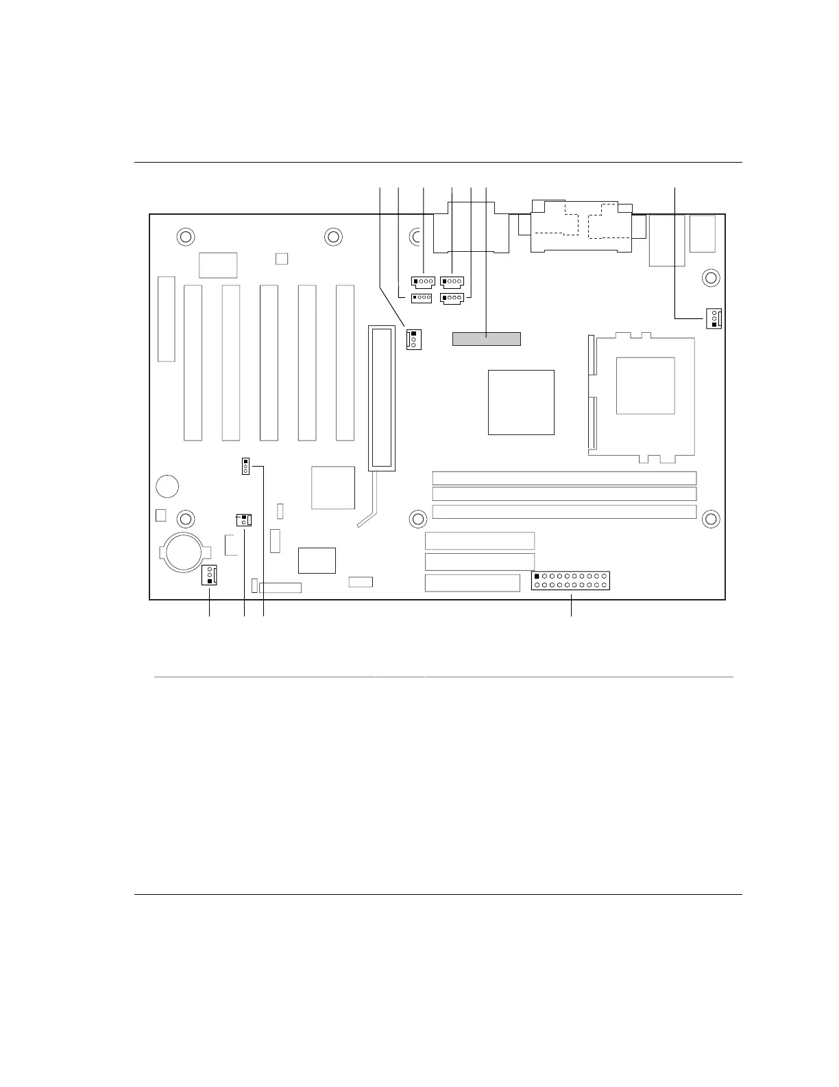
2.8.2.2 Audio, Video, Power, and Hardware Control Connectors
Figure 10 shows the location of the audio, video, power, and hardware control connectors.
OM10044
1
11
10
20
HK J I
1
1
1
1
1
1
1
1
FDECB GA
1
Item Description Color Reference Designator For more information see:
A Chassis Fan (Fan 2) N/A J3F1 Table 28
B CD-ROM, Legacy style, 2 mm White J2F2 Table 29
C ATAPI CD-ROM Black J2F1 Table 30
D Auxiliary line in, ATAPI style White J2G1 Table 31
E Telephony, ATAPI style Green J2G2 Table 32
F Digital video out N/A J3H1 Table 33
G Processor fan (Fan 3) N/A J3M1 Table 34
H Power N/A J8K1 Table 35
I Wake on LAN technology N/A J6B1 Table 36
J Chassis intrusion N/A J7B1 Table 37
K Chassis fan (Fan 1) N/A J8B1 Table 38
Figure 10. Audio, Video, Hardware Control, and Fan Connectors