Technical Reference
71
2.8.3.3 Front Panel Connector
This section describes the functions of the front panel connector. Table 48 lists the signal names
of the front panel connector.
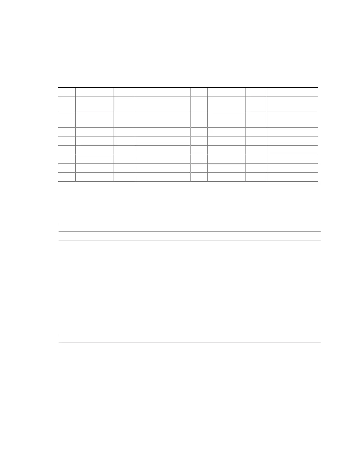
Table 48. Front Panel Connector (J8C3)
Pin Signal In/Out Description Pin Signal In/Out Description
1 HD_PWR Out Hard disk LED pull-
up (330 Ω) to +5 V
2 HDR_BLNK_
GRN
Out Front panel green
LED
3 HDA# Out Hard disk active LED 4 HDR_BLNK_
YEL
Out Front panel yellow
LED
5 GND Ground 6 FPBUT_IN In Power switch
7 FP_RESET# In Reset switch 8 GND Ground
9 +5 V Out IR Power 10 N/C
11 IRRX In IrDA serial input 12 GND Ground
13 GND Ground 14 (pin removed) Not connected
15 IRTX Out IrDA serial output 16 +5 V Out Power
2.8.3.3.1 Infrared Port Connector
Serial port B can be configured to support an IrDA module connected to pins 9, 11, 13, and 15.
For information about Refer to
Infrared support Section 1.7.2, page 26
Configuring serial port B for infrared applications Section 4.4.3, page 104
2.8.3.3.2 Reset Switch Connector
Pins 5 and 7 can be connected to a momentary SPST type switch that is normally open. When the
switch is closed, the D815EEA board resets and runs the POST.
2.8.3.3.3 Hard Drive Activity LED Connector
Pins 1 and 3 can be connected to an LED to provide a visual indicator that data is being read from
or written to a hard drive. For the LED to function properly, an IDE drive must be connected to
the onboard IDE interface. The LED will also show activity for devices connected to the SCSI
hard drive activity LED connector.
For information about Refer to
The SCSI hard drive activity LED connector Section 2.8.3.1, page 70
2.8.3.3.4 Power/Sleep/Message Waiting LED Connector
Pins 2 and 4 can be connected to a single- or dual-colored LED. Table 49 shows the possible
states for a single-colored LED. Table 50 shows the possible states for a dual-colored LED.