Intel
®
Desktop Board D815EEA Technical Product Specification
78
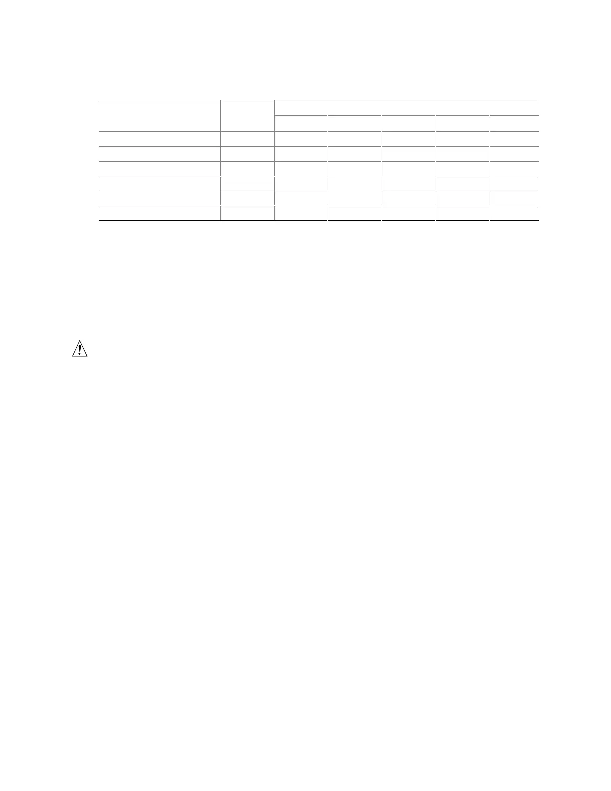
Table 53. Power Usage For Board with Enhanced PCI Audio Subsystem and no Onboard
LAN subsystem
DC Current at:
Mode AC Power +3.3 V +5 V +12 V -12 V +5 VSB
Windows 98 APM full on 43 W 1.80 A 2.81 A 0.18 A 0.00 A 0.09 A
Windows 98 APM Suspend 25 W 1.72 A 0.68 A 0.18 A 0.00 A 0.09 A
Windows 98 ACPI S0 30 W 1.82 A 0.68 A 0.18 A 0.02 A 0.09 A
Windows 98 ACPI S1 25 W 1.73 A 0.68 A 0.18 A 0.02 A 0.09 A
Windows 98 ACPI S3 1 W 0.0 A 0.0 A 0.0 A 0.0 A 0.23 A
Windows 98 ACPI Off 0 W 0.0 A 0.0 A 0.0 A 0.0 A 0.09 A
2.11.2 Add-in Board Considerations
The D815EEA board is designed to provide 2 A (average) of +5 V current for each add-in board.
The total +5 V current draw for add-in boards in a fully-loaded D815EEA board (all six expansion
slots filled) must not exceed 12 A.
2.11.3 Standby Current Requirements
CAUTION
Power supplies used with the board must provide enough standby current to support the Instantly
Available (ACPI S3 sleep state) configuration. If the standby current necessary to support
multiple wake events from the PCI and/or USB buses exceeds power supply capacity, the board
may lose register settings stored in memory and may not awaken properly.
To estimate the standby current required for a specific system configuration, the standby current
requirements of all installed components must be combined. Refer to Table 54 and follow these
steps:
1. List the board’s standby current requirement (767 mA).
2. List the PS/2 ports’ standby current requirement (see note below).
3. List, from the AGP and PCI 2.2 slots (wake enabled devices) row, the total number of wake-
enabled devices installed and multiply by the standby current requirement.
4. List, from the AGP and PCI 2.2 slots (non-wake enabled devices) row, the total number of
wake-enabled devices installed and multiply by the standby current requirement.
5. List all additional wake enabled devices’ and non-wake enabled devices’ standby current
requirements as applicable.
6. Add all the listed standby current totals from steps 1 through 5 to determine the total estimated
standby current power supply requirement.