Intel
®
Desktop Board D815EEA Technical Product Specification
70
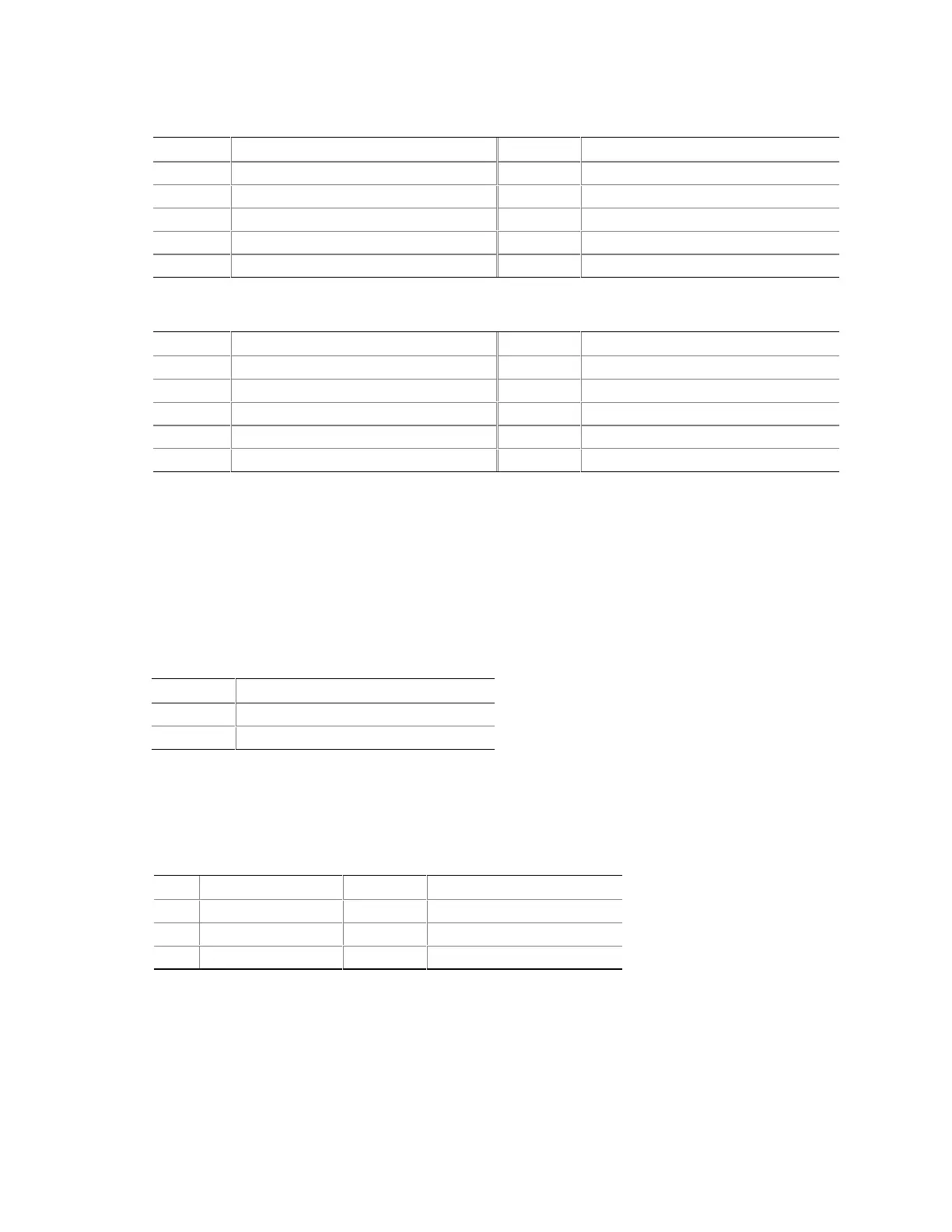
Table 44. Front Panel USB Connector (J8C1)
Pin Signal Name Pin Signal Name
1 VREG_FP_USB_PWR 2 VREG_FP_USB_PWR
3 ICH_U_P2# 4 ICH_U_P3#
5 ICH_U_P2 6 ICH_U_P3
7 Ground 8 Ground
9 Key (no pin) 10 ICU_U_OC1_2#
Table 45. Serial Port B Connector (J8E1)
Pin Signal Name Pin Signal Name
1 DCD2 2 Serial In# (SIN2#)
3 Serial Out# (SOUT2#) 4 DTR2
5 Ground 6 DSR2
7RTS2 8 CTS2
9 RI2 10 Key (no pin)
2.8.3.1 SCSI Hard Drive Activity LED Connector
The SCSI hard drive activity LED connector is a 1 x 2-pin connector that allows add-in
SCSI controller to use the same LED as the IDE controller. This connector can be connected to the
LED output of the add-in controller card. The LED will indicate when data is being read or written
using the add-in controller. Table 46 lists the signal names of the SCSI hard drive activity LED
connector.
Table 46. SCSI LED Connector (J7A1)
Pin Signal Name
1 SCSI activity
2 Not connected
2.8.3.2 Auxiliary Front Panel Power LED Connector
This connector duplicates the signals on pins 2 and 4 of the front panel connector.
Table 47. Auxiliary Front Panel Power LED Connector (J8C2)
Pin Signal Name In/Out Description
1 HDR_BLNK_GRN Out Front panel green LED
2 No connect
3 HDR_BLNK_YEL Out Front panel yellow LED