Electrical Specifications
38 Datasheet
that this differs from the VID employed by the processor during a power management event (Intel Thermal
Monitor 2, Enhanced Intel SpeedStep Technology, or Enhanced Halt State).
2. The voltage specifications are assumed to be measured across V
CC_SENSE
and V
SS_SENSE
pins at socket with
a 100-MHz bandwidth oscilloscope, 1.5-pF maximum probe capacitance, and 1-MΩ minimum impedance.
The maximum length of ground wire on the probe should be less than 5 mm. Ensure external noise from
the system is not coupled in the scope probe.
3. Specified at 105 °C T
J
.
4. Specified at the nominal V
CC
.
5. Measured at the bulk capacitors on the motherboard.
6. V
CC,BOOT
tolerance shown in Figure 7 and Figure 8.
7. Based on simulations and averaged over the duration of any change in current. Specified by design/
characterization at nominal V
CC
. Not 100% tested.
8. This is a power-up peak current specification that is applicable when V
CCP
is high and V
CC_CORE
is low.
9. This is a steady-state I
CC
current specification that is applicable when both V
CCP
and V
CC_CORE
are high.
10. Processor I
CC
requirements in Intel Dynamic Acceleration Technology mode are lesser than I
CC
in HFM
11. The maximum delta between Intel Enhanced Deeper Sleep and LFM on the processor will be lesser than or
equal to 300 mV.
12. Instantaneous current I
CC_CORE_INST
of 44 A has to be sustained for short time (t
INST
) of 35 µs. Average
current will be less than maximum specified I
CCDES
. VR OCP threshold should be high enough to support
current levels described herein.
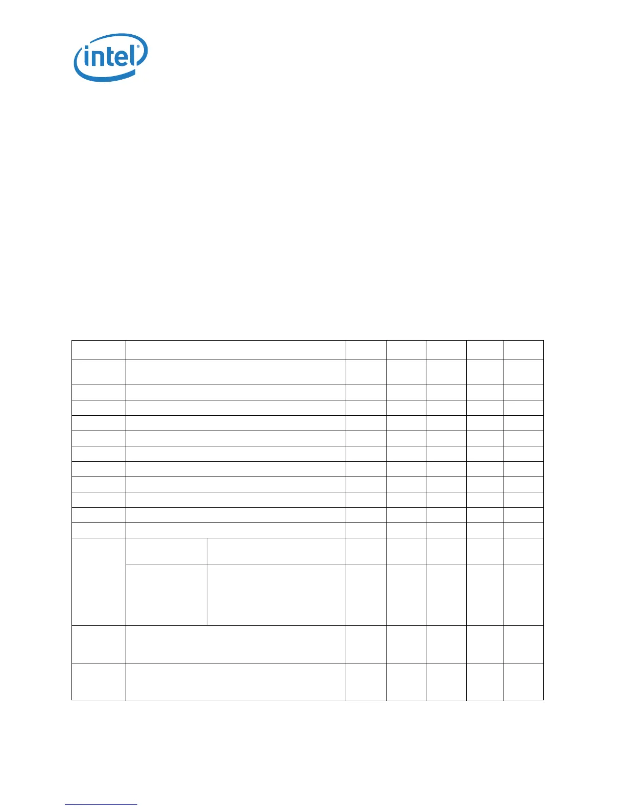
Table 10. Voltage and Current Specifications for the Dual-Core, Low-Voltage SFF
Processor
Symbol Parameter Min Typ Max Unit Notes
V
CCDAM
V
CC
in Enhanced Intel® Dynamic Acceleration
Technology Mode
0.9 — 1.25 V 1, 2
V
CCHFM
V
CC
at Highest Frequency Mode (HFM) 0.9 — 1.175 V 1, 2
V
CCLFM
V
CC
at Lowest Frequency Mode (LFM) 0.85 — 1.025 V 1, 2
V
CCSLFM
V
CC
at Super Low Frequency Mode (Super LFM) 0.75 — 0.95 V 1, 2
V
CC,BOOT
Default V
CC
Voltage for Initial Power Up — 1.20 — V 2, 6, 8
V
CCP
AGTL+ Termination Voltage 1.00 1.05 1.10 V
V
CCA
PLL Supply Voltage 1.425 1.5 1.575 V
V
CCDPRSLP
V
CC
at Deeper Sleep 0.65 — 0.85 V 1, 2
V
DC4
V
CC
at Intel® Enhanced Deeper Sleep State 0.6 — 0.85 V 1, 2
V
CCDPPWDN
V
CC
at Deep Power Down Technology State (C6) 0.35 — 0.7 V 1, 2
I
CCDES
I
CC
for Processors Recommended Design Target — — 27 A 5
I
CC
Processor
Number
Core Frequency/Voltage — — —
SL9600
SL9400
SL9300
2.13 GHz & V
CCHFM
1.86 GHz & V
CCHFM
1.6 GHz & V
CCHFM
1.6 GHz & V
CCLFM
0.8 GHz & V
CCSLFM
——
27
27
27
25.5
15
A3, 4, 12
I
AH,
I
SGNT
I
CC
Auto-Halt & Stop-Grant
HFM
SuperLFM
——12.3
8.2
A3, 4, 12
I
SLP
I
CC
Sleep
HFM
SuperLFM
——11.8
8.0
A3, 4, 12