Package Mechanical Specifications and Pin Information
96 Datasheet
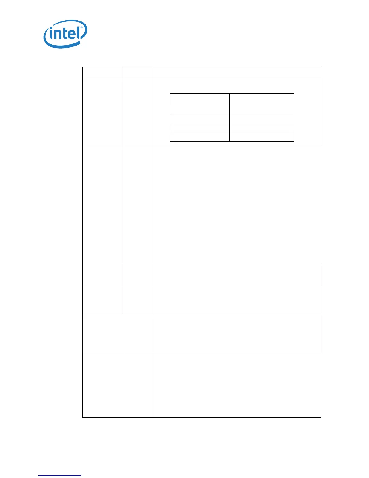
DSTBP[3:0]#
Input/
Output
Data strobe used to latch in D[63:0]#.
FERR#/PBE# Output
FERR# (Floating-point Error)/PBE# (Pending Break Event) is a
multiplexed signal and its meaning is qualified with STPCLK#. When
STPCLK# is not asserted, FERR#/PBE# indicates a floating point
when the processor detects an unmasked floating-point error.
FERR# is similar to the ERROR# signal on the Intel® 387
coprocessor, and is included for compatibility with systems using
Microsoft MS-DOS*-type floating-point error reporting. When
STPCLK# is asserted, an assertion of FERR#/PBE# indicates that
the processor has a pending break event waiting for service. The
assertion of FERR#/PBE# indicates that the processor should be
returned to the Normal state. When FERR#/PBE# is asserted,
indicating a break event, it will remain asserted until STPCLK# is
deasserted. Assertion of PREQ# when STPCLK# is active will also
cause an FERR# break event.
For additional information on the pending break event functionality,
including identification of support of the feature and enable/disable
information, refer to Volumes 3A and 3B of the Intel® 64 and IA-32
Architectures Software Developer's Manuals and the Intel®
Processor Identification and CPUID Instruction application note.
GTLREF Input
GTLREF determines the signal reference level for AGTL+ input pins.
GTLREF should be set at 2/3 V
CCP
. GTLREF is used by the AGTL+
receivers to determine if a signal is a logical 0 or logical 1.
HIT#
HITM#
Input/
Output
Input/
Output
HIT# (Snoop Hit) and HITM# (Hit Modified) convey transaction
snoop operation results. Either FSB agent may assert both HIT#
and HITM# together to indicate that it requires a snoop stall that
can be continued by reasserting HIT# and HITM# together.
IERR# Output
IERR# (Internal Error) is asserted by the processor as the result of
an internal error. Assertion of IERR# is usually accompanied by a
SHUTDOWN transaction on the FSB. This transaction may optionally
be converted to an external error signal (e.g., NMI) by system core
logic. The processor will keep IERR# asserted until the assertion of
RESET#, BINIT#, or INIT#.
IGNNE# Input
IGNNE# (Ignore Numeric Error) is asserted to force the processor
to ignore a numeric error and continue to execute non-control
floating-point instructions. If IGNNE# is deasserted, the processor
generates an exception on a non-control floating-point instruction if
a previous floating-point instruction caused an error. IGNNE# has
no effect when the NE bit in control register 0 (CR0) is set.
IGNNE# is an asynchronous signal. However, to ensure recognition
of this signal following an input/output write instruction, it must be
valid along with the TRDY# assertion of the corresponding input/
output Write bus transaction.
Table 19. Signal Description (Sheet 4 of 8)
Name Type Description
Signals Associated Strobe
D[15:0]#, DINV[0]# DSTBP[0]#
D[31:16]#, DINV[1]# DSTBP[1]#
D[47:32]#, DINV[2]# DSTBP[2]#
D[63:48]#, DINV[3]# DSTBP[3]#