Design and Environmental Specifications Intel® Server Board S3420GP TPS
Revision 2.4
Intel order number E65697-010
100
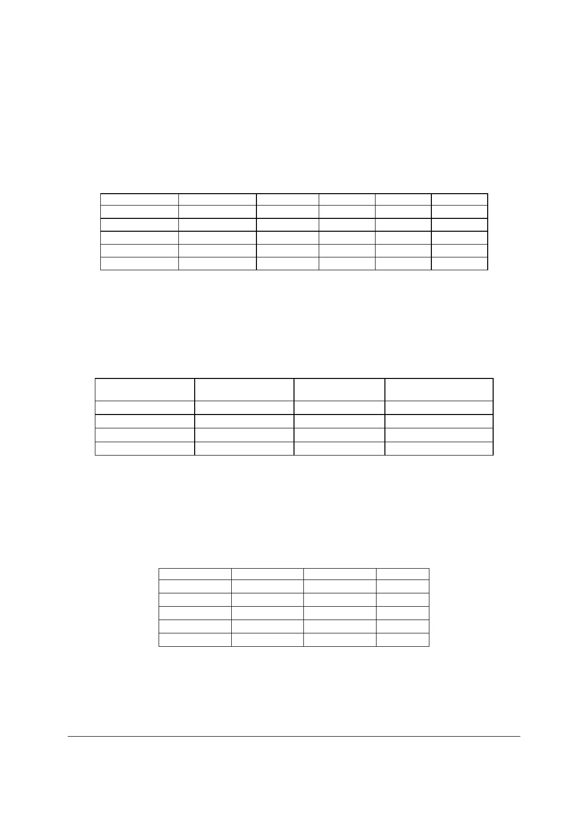
10.4.4 Voltage Regulation
The power supply output voltages must stay within the following voltage limits when operating at
steady state and dynamic loading conditions. These limits include the peak-peak ripple/noise.
All outputs are measured with reference to the return remote sense signal (ReturnS).
Table 65. Voltage Regulation Limits
Parameter Tolerance Minimum Normal Maximum Units
+ 3.3 V - 5%/+5% +3.14 +3.30 +3.46 Vrms
+ 5 V - 5%/+5% +4.75 +5.00 +5.25 Vrms
+ 12 V - 5%/+5% +11.40 +12.00 +12.60 Vrms
- 12 V - 10%/+10% -13.20 -12.00 -10.80 Vrms
+ 5 VSB - 5%/+5% +4.75 +5.00 +5.25 Vrms
10.4.5 Dynamic Loading
The output voltages remain within limits for the step loading and capacitive loading specified in
the following table. The load transient repetition rate is tested between 50 Hz and 5 kHz at duty
cycles ranging from 10%-90%. The load transient repetition rate is only a test specification. The
step load may occur anywhere within the Min load to the Max load conditions.
Table 66. Transient Load Requirements
Output Step Load Size
(See note 1)
Load Slew Rate Test capacitive Load
+3.3 V 5.0 A
0.25 A/sec 250 F
+5 V 6.0 A
0.25 A/sec 400 F
12 V 11.0 A
0.25 A/sec 500 F
+5 VSB 0.5 A
0.25 A/sec 20 F
Notes:
1.
Step loads on each 12 V output may happen simultaneously and should be tested that way.
10.4.6 Capacitive Loading
The power supply is stable and meets all requirements with the following capacitive loading
ranges.
Table 67. Capacitve Loading Conditions
Output Minimum
Maximum
Units
+3.3 V 100 2200
F
+5 V 400 2200
F
+12 V 500 2200
F
-12 V 1 350
F
+5 VSB 20 350
F
10.4.7 Closed-loop Stability
The power supply is unconditionally stable under all line/load/transient load conditions including
capacitive load ranges. A minimum of 45° phase margin and -10 dB-gain margin is required.
The power supply manufacturer provides proof of the unit’s closed-loop stability with local

 Loading...


