Intel® Server Board S3420GP TPS Connector/Header Locations and Pin-outs
Revision 2.4
Intel order number E65697-010
77
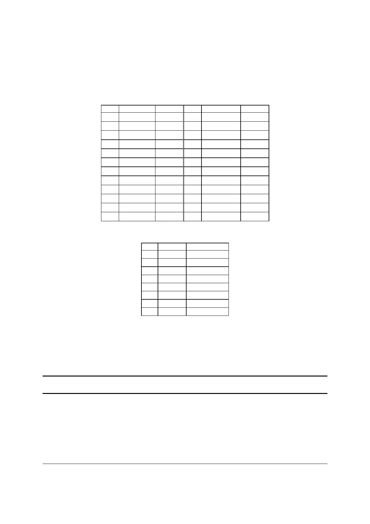
The following tables define the connector pin-outs.
Table 39. Baseboard Power Connector Pin-out (J9A1)
Pin Signal Color Pin Signal Color
1 +3.3 Vdc Orange 13 +3.3 Vdc Orange
2 +3.3 Vdc Orange 14 -12 Vdc Blue
3 GND Black 15 GND Black
4 +5 Vdc Red 16 PS_ON# Green
5 GND Black 17 GND Black
6 +5 Vdc Red 18 GND Black
7 GND Black 19 GND Black
8 PWRGD_PS Gray 20 NC White
9 5 VSB Purple 21 +5 Vdc Red
10 +12 Vdc Yellow 22 +5 Vdc Red
11 +12 Vdc Yellow 23 +5 Vdc Red
12 +3.3 Vdc Orange 24 GND Black
Table 40. SSI Processor Power Connector Pin-out (J9C1)
Pin
Signal
Color
1 GND Black
2 GND Black
3 GND Black
4 GND Black
5 +12 Vdc Yellow/black
6 +12 Vdc Yellow/black
7 +12 Vdc Yellow/black
8 +12 Vdc Yellow/black
7.3 System Management Headers
7.3.1 Intel
®
Remote Management Module 3 (Intel
®
RMM3) Connector
A 34-pin Intel
®
RMM 3 connector (J2C1) is included on the server board to support the optional
Intel
®
Remote Management Module 3. This server board does not support third-party
management cards.
Note: This connector is not compatible with the Intel
®
Remote Management Module (Intel
®
RMM) or the Intel
®
Remote Management Module 2 (Intel
®
RMM2).

 Loading...


