Intel® Server Board S3420GP TPS Connector/Header Locations and Pin-outs
Revision 2.4
Intel order number E65697-010
85
Pin Signal Name
Description
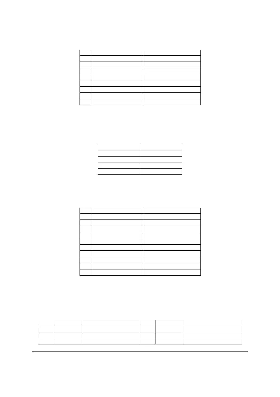
3 USB_ICH_P4N_CONN USB port 4 negative signal
4 USB_ICH_P5N_CONN USB port 5 negative signal
5 USB_ICH_P4P_CONN USB port 4 positive signal
6 USB_ICH_P5P_CONN USB port 5 positive signal
7 Ground
8 Ground
9 Key No pin
10 TP_USB_ICH_NC Test point
One x connector (J1J2) on the server board provides an option to support a USB floppy
connector.
Table 55. Pin-out of Internal USB Connector for Floppy ( J1J2)
Pin Signal Name
1 +5V
2 USB_N
3 USB_P
4 GND
One 2x5 connectors (J3F2) on the server board provides an option to support an Intel
®
Z-U130
Value Solid State Drive. The following table defines the pin-out of the connector.
Table 56. Pin-out of Internal USB Connector for low-profile Intel
®
Z-U130 Value Solid State Drive
(J3F2)
Pin Signal Name Description
1 +5V USB power
2 NC N/A
3 USB Data - USB port ## negative signal
4 NC N/A
5 USB Data + USB port ## positive signal
6 NC N/A
7 Ground N/A
8 NC N/A
9 Key No pin
10 LED# Activity LED
7.6 PCI Express* Slot/PCI Slot/Riser Card Slot
A PCI-E Riser card will enable a PCI-E add-on card to be accommodated in the 1U chassis.
The following table shows the pin-out for this riser slot.
Table 57. Pin-out of adaptive riser slot/PCI Express slot 6
Pin Signal Description Pin
Signal Description
B1 +12V P12V A1 PRSNT1_N GND
B2 +12V P12V A2 +12V P12V
B3 RSVD P12V A3 +12V P12V

 Loading...


