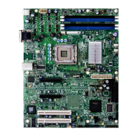
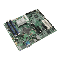
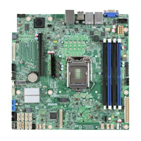
Intel® Server Board S3420GP TPS Connector/Header Locations and Pin-outs
Revision 2.4
Intel order number E65697-010
79
7.3.4 SGPIO Header
Table 44. SGPIO Header Pin-out (J1J3)
Pin Signal Name
Description
1 SGPIO_CLOCK SGPIO Clock Signal
2 SGPIO_LOAD SGPIO Load Signal
3 SGPIO_DATAOUT0 SGPIO Data Out
4 SGPIO_DATAOUT1 SGPIO Data In
7.4 Front Control Panel Connector
The server board provides a 24-pin SSI front panel connector (J1C1) for use with Intel
®
and
third-party chassis. The following table provides the pin-out for this connector.
Table 45. Front Panel SSI Standard 24-pin Connector Pin-out (J1C1)
Pin Signal Name Description Pin Signal Name Description
1 P3V3_AUX
(Power_LED_Anode)
Power LED + 2 P3V3_STBY Front Panel
Power
3 Key No Connection 4 P5V_STBY (ID LED
Anode)
ID LED +
5 FP_PWR_LED_N Power LED - 6 FP_ID_LED_BUF_N ID LED -
7 P3V3
(HDD_ACTIVITY_Anode)
HDD Activity
LED+
8 FP_LED_STATUS_GR
EEN_N
Status LED
Green -
9 LED_HDD_ACTIVITY_N HDD Activity
LED-
10 FP_LED_STATUS_AM
BER_N
Status LED
Amber
11 FP_PWR_BTN_N Power Button 12 NIC1_ACT_LED_N NIC 1 Activity
LED -
13 GND (Power Button
GND)
Power Button
Ground
14 NIC1_LINK_LED_N NIC 1 Link LED -
15 RST_FP_BTN_N Reset Button 16 SMB_SENSOR_3V3ST
B_DATA
SMB Sensor
DATA
17 GND (Reset GND) Reset Button
Ground
18 SMB_SENSOR_3V3ST
B_CLK
SMB Sensor
Clock
19 FP_ID_BTN_N ID Button 20 FP_CHASS_INTRU Chassis Intrusion
21 PU_FM_SIO_TEMP_SE
NSOR
Front Panel
Temperature
Sensor
22 NIC2_ACT_LED_N NIC 2 Activity
LED -
23 FP_NMI_BTN_N NMI Button 24 NIC2_LINK_LED_N NIC 2 Link LED -
Combined system BIOS and the Integrated BMC support provide the functionality of the various
supported control panel buttons and LEDs. The following sections describe the supported
functionality of each control panel feature.
Note: Control panel features are also routed through the bridge board connector at location
J1C1 as is implemented in Intel
®
Server Systems configured using a bridge board and a hot-
swap backplane.

 Loading...
