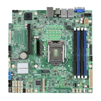
Table of Contents Intel® Server Board S3420GP TPS
Revision 2.4
Intel order number E65697-010
vi
7.3.4 SGPIO Header ........................................................................................................ 79
7.4 Front Control Panel Connector ............................................................................... 79
7.4.1 Power Button ........................................................................................................... 80
7.4.2 Reset Button ............................................................................................................ 80
7.4.3 NMI Button ............................................................................................................... 80
7.4.4 System Status Indicator LED .................................................................................. 80
7.5 I/O Connectors ........................................................................................................ 81
7.5.1 VGA Connector ....................................................................................................... 81
7.5.2 Rear NIC and USB connector ................................................................................. 82
7.5.3 SATA ....................................................................................................................... 83
7.5.4 50-pin PCI Express* Connector .............................................................................. 83
7.5.5 Serial Port Connectors ............................................................................................ 84
7.5.6 USB Connector ....................................................................................................... 84
7.6 PCI Express* Slot/PCI Slot/Riser Card Slot / ......................................................... 85
7.7 Fan Headers ............................................................................................................ 90
8. Jumper Blocks...................................................................................................................... 91
8.1 CMOS Clear and Password Reset Usage Procedure ............................................ 92
8.1.1 Clearing the CMOS ................................................................................................. 92
8.1.2 Clearing the Password ............................................................................................ 92
8.2 Integrated BMC Force Update Procedure (only for the Intel
®
Server Board
S3420GPLX and S3420GPLC) ................................................................................................. 93
8.3 ME Force Update Jumper ....................................................................................... 93
8.4 BIOS Recovery Jumper .......................................................................................... 94
9. Intel
®
Light Guided Diagnostics ......................................................................................... 95
9.1 System Status LED (For the Intel
®
Server Board S3420GPLX and S3420GPLC) 95
9.2 Post Code Diagnostic LEDs .................................................................................... 96
10. Design and Environmental Specifications ........................................................................ 97
10.1 Intel
®
Server Board S3420GP Design Specifications ............................................. 97
10.2 Board-level Calculated MTBF ................................................................................. 97
10.3 Server Board Power Requirements ........................................................................ 98
10.3.1 Processor Power Support ....................................................................................... 98
10.4 Power Supply Output Requirements ...................................................................... 99
10.4.1 Grounding ................................................................................................................ 99
10.4.2 Standby Outputs ...................................................................................................... 99
10.4.3 Remote Sense ......................................................................................................... 99
10.4.4 Voltage Regulation ................................................................................................ 100
10.4.5 Dynamic Loading ................................................................................................... 100
10.4.6 Capacitive Loading ................................................................................................ 100
10.4.7 Closed-loop Stability ............................................................................................. 100
10.4.8 Common Mode Noise ........................................................................................... 101
10.4.9 Ripple/Noise .......................................................................................................... 101

 Loading...
