Reference Number: 327043-001 11
Introduction
1.4 Uncore PMON - Typical Control/Counter Logic
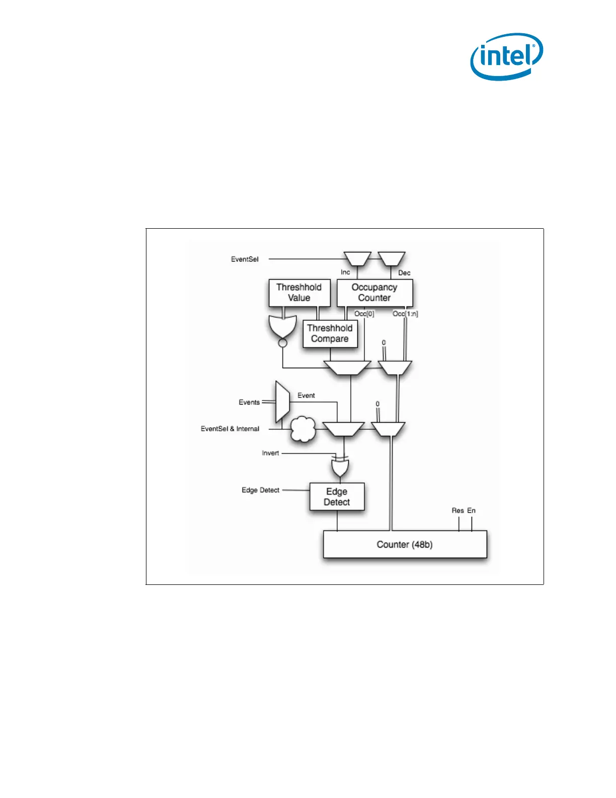
Following is a diagram of the standard perfmon counter block illustrating how event information is
routed and stored within each counter and how its paired control register helps to select and filter the
incoming information. Details for how control bits affect event information is presented in each of the
box subsections of Chapter 2, with some summary information below.
Note: The PCU uses an adaptation of this block (refer to Section 2.6.3, “PCU Performance
Monitors” more information). Also note that only a subset of the available control bits
are presented in the diagram.
Selecting What To Monitor: The main task of a configuration register is to select the event to be
monitored by its respective data counter. Setting the .ev_sel and .umask fields performs the event
selection.
Telling HW that the Control Register Is Set: .en bit must be set to 1 to enable counting. Once
counting has been enabled in the box and global level of the Performance Monitoring Hierarchy (refer
to Section 2.1.1, “Setting up a Monitoring Session” for more information), the paired data register will
begin to collect events.
Figure 1-2. Perfmon Control/Counter Block Diagram