Intel® Xeon® Processor E5-2600 Product Family Uncore Performance Monitoring
60 Reference Number: 327043-001
For information on how to setup a monitoring session, refer to Section 2.1, “Uncore Per-Socket
Performance Monitoring Control”.
2.5.4 iMC Performance Monitors
2.5.4.1 MC Box Level PMON State
The following registers represent the state governing all box-level PMUs in the MC Boxes.
In the case of the MC, the MC_CHy_PCI_PMON_BOX_CTL register governs what happens when a
freeze signal is received (.frz_en). It also provides the ability to manually freeze the counters in the
box (.frz) .
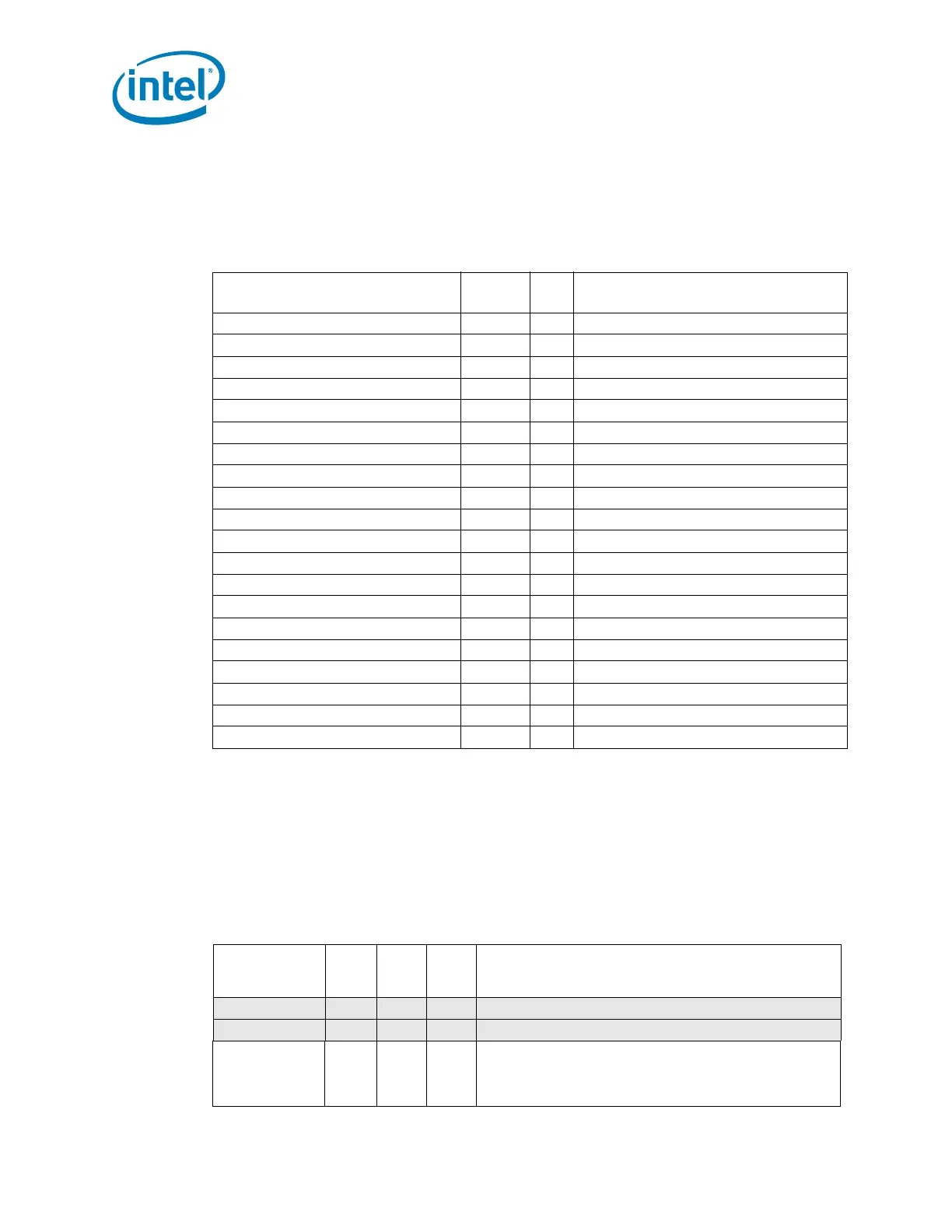
Table 2-59. iMC Performance Monitoring MSRs
Register Name
PCICFG
Address
Size
(bits)
Description
PCICFG Base Address Dev:Func
MC Channel 0 PMON Registers D16:F0
MC Channel 1 PMON Registers D16:F1
MC Channel 2 PMON Registers D16:F4
MC Channel 3 PMON Registers D16:F5
Box-Level Control/Status
MC_CHy_PCI_PMON_BOX_CTL F4 32 MC Channel y PMON Box-Wide Control
Generic Counter Control
MC_CHy_PCI_PMON_FIXED_CTL F0 32 MC Channel y PMON Control for Fixed Counter
MC_CHy_PCI_PMON_CTL3 E4 32 MC Channel y PMON Control for Counter 3
MC_CHy_PCI_PMON_CTL2 E0 32 MC Channel y PMON Control for Counter 2
MC_CHy_PCI_PMON_CTL1 DC 32 MC Channel y PMON Control for Counter 1
MC_CHy_PCI_PMON_CTL0 D8 32 MC Channel y PMON Control for Counter 0
Generic Counters
MC_CHy_PCI_PMON_FIXED_CTR D4+D0 32x2 MC Channel y PMON Fixed Counter
MC_CHy_PCI_PMON_CTR3 BC+B8 32x2 MC Channel y PMON Counter 3
MC_CHy_PCI_PMON_CTR2 B4+B0 32x2 MC Channel y PMON Counter 2
MC_CHy_PCI_PMON_CTR1 AC+A8 32x2 MC Channel y PMON Counter 1
MC_CHy_PCI_PMON_CTR0 A4+A0 32x2 MC Channel y PMON Counter 0
Table 2-60. MC_CHy_PCI_PMON_BOX_CTL Register – Field Definitions (Sheet 1 of 2)
Field Bits Attr
HW
Reset
Val
Description
rsv 31:18 RV 0 Reserved (?)
rsv 17 RV 0 Reserved; SW must write to 0 else behavior is undefined.
frz_en 16 WO 0 Freeze Enable.
If set to 1 and a freeze signal is received, the counters will be
stopped or ‘frozen’, else the freeze signal will be ignored.