Reference Number: 327043-001 27
Intel® Xeon® Processor E5-2600 Product Family Uncore Performance Monitoring
2.3.3.1 CBo Box Level PMON State
The following registers represent the state governing all box-level PMUs in the CBo.
In the case of the CBo, the Cn_MSR_PMON_BOX_CTL register governs what happens when a freeze
signal is received (.frz_en). It also provides the ability to manually freeze the counters in the box
(.frz) and reset the generic state (.rst_ctrs and .rst_ctrl).
U
2.3.3.2 CBo PMON state - Counter/Control Pairs
The following table defines the layout of the CBo performance monitor control registers. The main
task of these configuration registers is to select the event to be monitored by their respective data
counter (.ev_sel, .umask). Additional control bits are provided to shape the incoming events (e.g.
.invert, .edge_det, .thresh) as well as provide additional functionality for monitoring software (.rst).
C7_MSR_PMON_CTL3 0x0DF3 32 CBo 7 PMON Control for Counter 3
C7_MSR_PMON_CTL2 0x0DF2 32 CBo 7 PMON Control for Counter 2
C7_MSR_PMON_CTL1 0x0DF1 32 CBo 7 PMON Control for Counter 1
C7_MSR_PMON_CTL0 0x0DF0 32 CBo 7 PMON Control for Counter 0
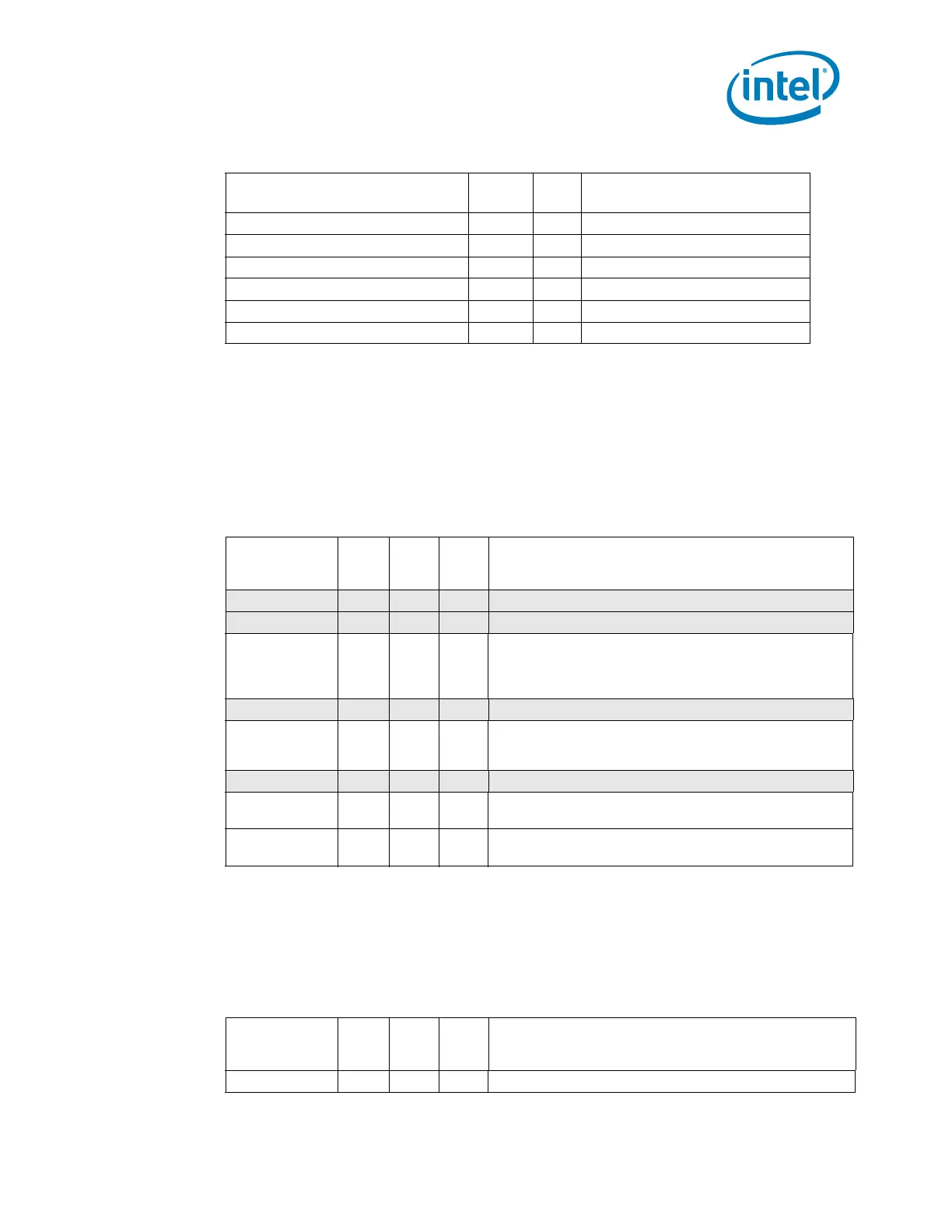
Box-Level Control/Status
C7_MSR_PMON_BOX_CTL 0x0DE4 32 CBo 7 PMON Box-Wide Control
Table 2-9. Cn_MSR_PMON_BOX_CTL Register – Field Definitions
Field Bits Attr
HW
Reset
Val
Description
rsv 31:18 RV 0 Reserved (?)
rsv 17 RV 0 Reserved; SW must write to 0 else behavior is undefined.
frz_en 16 WO 0 Freeze Enable.
If set to 1 and a freeze signal is received, the counters will be
stopped or ‘frozen’, else the freeze signal will be ignored.
rsv 15:9 RV 0 Reserved (?)
frz 8 WO 0 Freeze.
If set to 1 and the .frz_en is 1, the counters in this box will be
frozen.
rsv 7:2 RV 0 Reserved (?)
rst_ctrs 1 WO 0 Reset Counters.
When set to 1, the Counter Registers will be reset to 0.
rst_ctrl 0 WO 0 Reset Control.
When set to 1, the Counter Control Registers will be reset to 0.
Table 2-10. Cn_MSR_PMON_CTL{3-0} Register – Field Definitions (Sheet 1 of 2)
Field Bits Attr
HW
Reset
Val
Description
thresh 31:24 RW-V 0 Threshold used in counter comparison.
Table 2-8. CBo Performance Monitoring MSRs (Sheet 4 of 4)
MSR Name
MSR
Address
Size
(bits)
Description