Chapter 1: Installation
14 CDC4 Door Controller Installation and Programming Manual
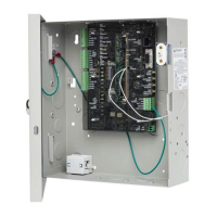
(3) Earth terminal. Connect the power earth wire from the enclosure mains transformer to the
earth terminal. Data cable shields can also be connected. See “Local data buses” on page
26.
(4) Battery 1 terminals. See “Batteries” on page 24.
(5) Battery 2 terminals. See “Batteries” on page 24.
(6) Auxiliary power output. See “Auxiliary power terminals” on page 26.
(7) Siren output. See “Siren” on page 26.
(8) ATS system bus. See “System data bus” on page 26.
(9) Tamper switch input. Connect the T and C terminals to the panel tamper switch in the
enclosure. Short circuit for inactive, open circuit for active. Must be shortened if not used.
Can only be used with normally closed contacts such as the panel tamper switches.
(10) Relay and lock power connections for four doors. Refer to “Door lock relay wiring” on page
29.
(11) Earth terminal. See “Earthing” on page 21.
(12) Input terminals. See “Inputs” on page 30.
(13) Output expansion connector. See “Output expansion” on page 30.
(14) PWR link. Power link for relay expansion cards. See “Output expansion” on page 30.
(15) Micro-B USB port.
(16) Ethernet port.
(17) Heart beat LED. See “LED indications” on page 32.
(18) Bus 1 quick connect header. See “Local data buses” on page 26.
(19) Bus 2 connector. See “Local data buses” on page 26.
(20) Bus 1 connector. See “Local data buses” on page 26.
(21) Bus 1 quick connect header. See “Local data buses” on page 26.
(22) Lock power 2 quick connect header. See “Local data buses” on page 26.
(23) Bus 1 Rx LED. See “LED indications” on page 32.
(24) Bus 1 Tx LED. See “LED indications” on page 32.
(25) Bus 1 TERM link. See “Bus termination” on page 28.
(26) Bus 2 Rx LED. See “LED indications” on page 32.
(27) Bus 2 Tx LED. See “LED indications” on page 32.
(28) Bus 2 TERM link. See “Bus termination” on page 28.
(29) System bus Rx LED. See “LED indications” on page 32.
(30) System bus Tx LED. See “LED indications” on page 32.
(31) System bus TERM link. See “Bus termination” on page 28.
(32) Lock power 1 quick connect header. See “Local data buses” on page 26.
(33) 10/100 Mbps LED. See “LED indications” on page 32.
(34) Ethernet link active LED. See “LED indications” on page 32.
(35) Test links (not fitted during normal operations). See “Defaulting the door controller” on page
34.
(36) System ready LEDs. See “LED indications” on page 32.
(37) Address selection DIP switch. Refer to “DIP switch settings” on page 23.
(38) Relay coil active LEDs. See “LED indications” on page 32.
Table 1: Connection details for terminal blocks
Mains transformer: 20 V AC power
Mains transformer: Power earth wire
12 V battery (the cable is fused)
12 V battery (the cable is fused)
8 Ω siren speaker or two 8 Ω siren speakers in parallel, or
12 V DC device and 1 kΩ 1/4 W resistor