Intermec EasyCoder 501 – Service Manual Ed. 7
152
Chapter 18 "uart1:"
1
/. Caution! Be careful not to enable the
external 5V unintentionally, which may
cause harm to the terminal, PC, or other
device connected to this port!
IC-207
DI
RO
RI+
RI-
DO+
DO-
+ RS422 IN
- RS422 IN
+ RS422 OUT
- RS422 OUT
15
17
19
21
P-201
("uart1:")
+5V +5V
P-208 P-209
P-206 P-207
P-204 P-205
/TXD
/RXD
4.7k
4.7k
100
100
4.7k
4.7k
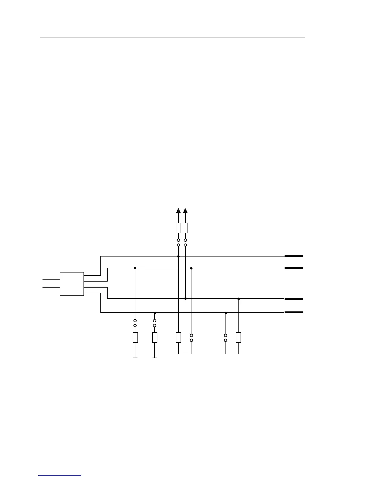
18.3 RS-422, cont.
On the CPU board, check:
• An optional RS-422 circuit must be fi tted on IC-207.
• Jumper must be fi tted on the lowest position of P-202 to select
RS 422.
• Jumper must be fi tted on some of P-204 to P-209 according to
diagram below.
• RS-232 circuit on IC-200 (standard), jumper on P-200, and
optcouplers on IC-205 and IC-206 (optional) are of no conse-
quence.
P-203 External 5 Volt
1
:
Jumper fi tted connects +5V to pin 16. Caution! Max. 200 mA.
(Note that +5V requires an additional wire in the cable).
P-204 – P-209 Communication straps:
Jumpers can be fi tted on P-204, P-205, P-206, P-207, P-208,
and/or P-209 in order to adapt the RS-422 communication to the
host, as shown in the diagram below. Normally, jumpers should be
fi tted on P-205, P-207, and P-209.