167Intermec EasyCoder 501 – Service Manual Ed. 7
Chapter 21 RS-422/485 Interface Board
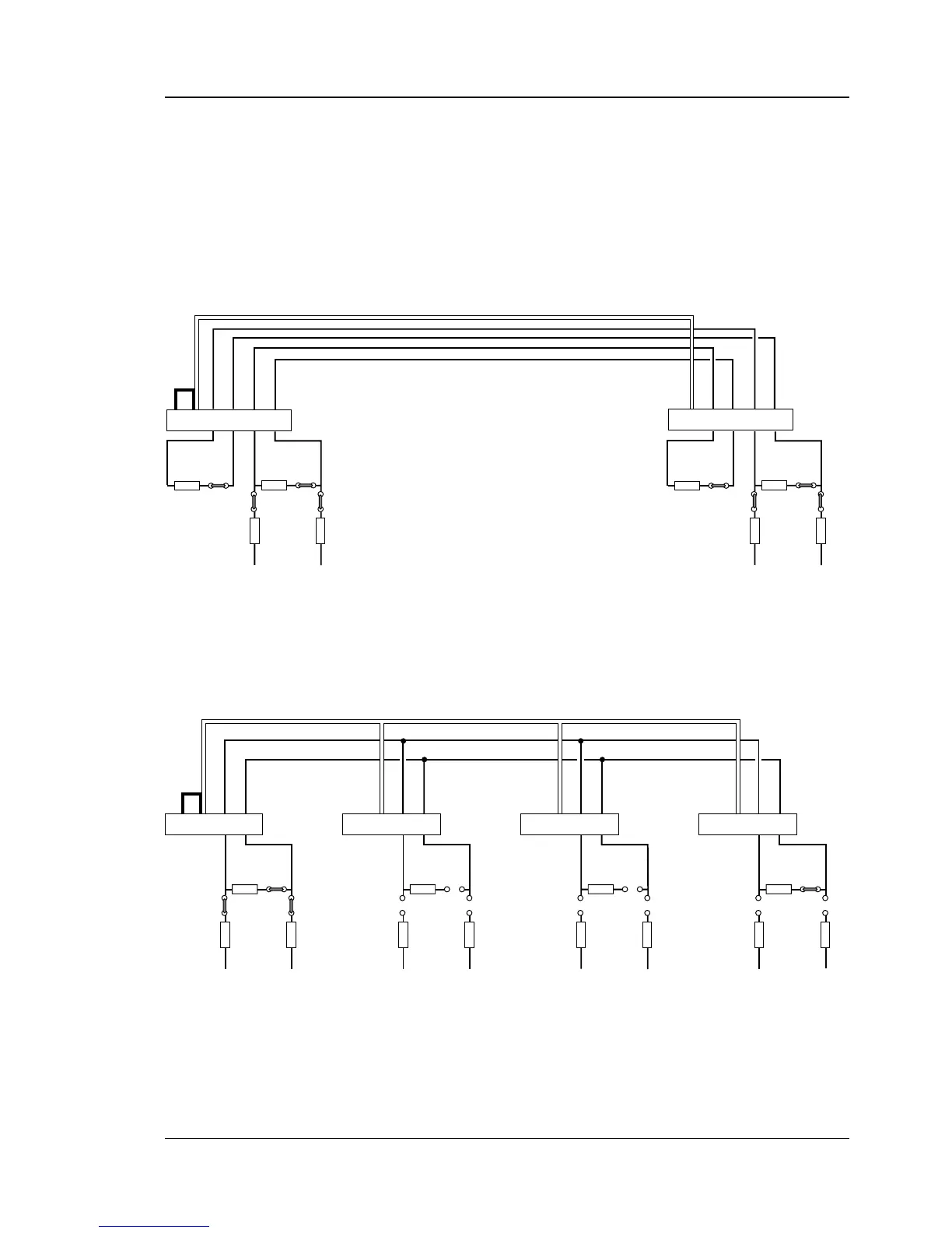
21.2 Straps, cont.
The illustrations below show how the voltage reference straps
and terminating resistor straps should be fi tted on the RS-422/485
interface boards. When a computer is connected to the line or loop,
the same principles apply. Refer to the computer manuals for infor-
mation on how to appoint the computer “master” and how to set
the termination.
100 ohm
17
+
19
-
21 7
+
19
-
21
7
+
19
-
21
7
+
19
-
21
Screen
Screen
Screen
Screen
P-10
P-8
P-2
P-9
+VEE GNDE
100 ohm
P-10
P-8
P-2
P-9
+VEE GNDE
100 ohm
P-10
P-8
P-2
P-9
+VEE GNDE
PRINTER
100 ohm
P-10
P-8
P-2
P-9
+VEE GNDE
PRINTERPRINTERPRINTER (master)
RS-485 MULTIDROP LOOP
(w. printer as master unit)
Screened twisted 2-line cable (approx. 50 pf/m)
P-8 and P-9 strapped on master unit.
P-10 strapped on first unit.
Connection P-2 pin 7 to Chassis GND
(for example P-2 pin 1) on one unit only.
No straps No straps P-10 strapped on last unit.
100 ohm100 ohm
P-10P-11
P-8P-9
+VEE GNDE
100 ohm100 ohm
17
+
19
-
21
+
15
-
17 7
+
19
-
21
+
15
-
17
Screen
Screen
P-10P-11
P-8
P-2
P-9
+VEE GNDE
P-2PRINTER
RS-422 POINT-TO-POINT
(printer to printer)
Screened twisted 4-line cable (approx. 50 pf/m)
P-8 and P-9 strapped on both units.
P-10 and P-11 strapped on both units.
Connection P-2 pin 7 to Chassis GND
(for example P-2 pin 1) on one unit only.
PRINTER
P-8 and P-9 strapped on both units.
P-10 and P-11 strapped on both units.