18 of 54
Version 2.4 (03/2020) Online
Translation of the original operating manual
Product information
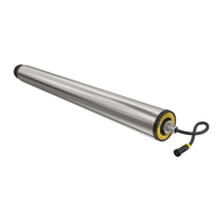
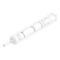
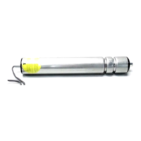
3.3 RollerDrive EC5000 BI with CAN bus
The CAN bus communication of the EC5000 BI is based on the following CAN/CANopen standards:
• ISO 11898-1 Road vehicles - Controller area network (CAN) - Part 1: Data link layer and physical signalling
• ISO 11898-2 Controller area network (CAN) - Part 2: High-speed medium access unit
• EN 50325 Industrial communications subsystem based on ISO 11898 (CAN) for controller-device interfaces -
Part1:Generalrequirements
• CiA 402 CANopen device prole for drives and motion control
CAN bus communication enables, among other things, the actual values of the RollerDrive to be read out (monitoring),
including:
• Number of starts/stops
• Operating hours (ready for operation)
• Runtime (time during which motor is rotating)
• Minimum temperature
• Maximum temperature
• Actual temperature
• Number of quick stops
• Average power
• Number of revolutions
So-called health indicator lights and service life indicator lights have also been integrated, which can be evaluated via
the connected Interroll MultiControl BI or a connected PLC.
Service life indicator lights
In accordance with statistically determined reference values, a signal is output when the RollerDrive reaches a service
life at which a replacement is recommended.
This is not a xed value that decreases with the runtime.
The expected service life increases or decreases depending on the load on the RollerDrive.
The service life indicator lights have two statuses:
Green The RollerDrive has not yet reached its expected service life.
Yellow The RollerDrive has reached its expected service life. Replacement is recommended.
Red This status is not used.