34 of 54
Version 2.4 (03/2020) Online
Translation of the original operating manual
Product information
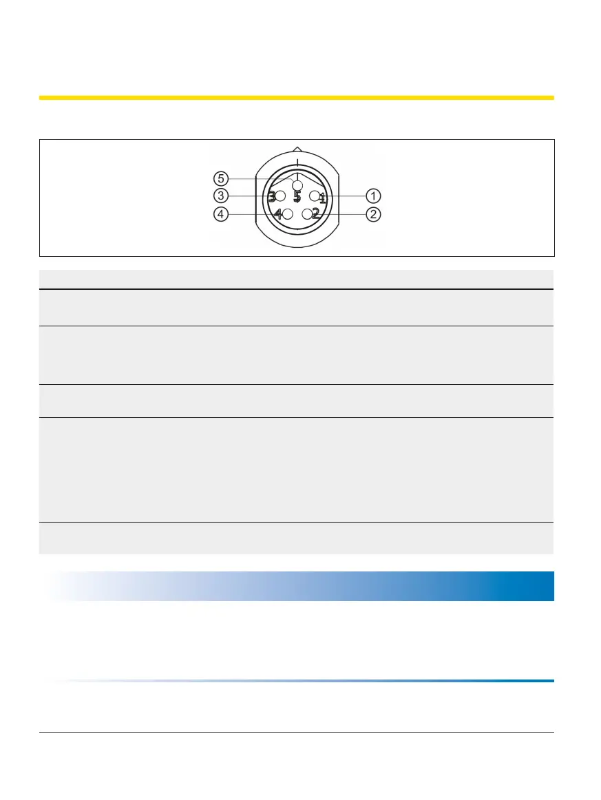
3.10 RollerDrive connector AI
Pin Colour Function Value
1 Brown Input of the power supply
(+)
Rated voltage:
Voltage range:
24 V DC
18 to 28 V DC
48 V DC
36 to 56 V DC
2 White Input of the rotational
direction as seen from the
end of the cable of the
RollerDrive
"Low" = anti-clockwise
"High" = clockwise
3 Blue Earth for power supply and
signal (-)
Earth
4 Black Error output Open collector
U
CESAT
= 0.5 V DC at I
C
= 5 mA
U
MAX
= 30 V DC
I
CMAX
= 5 mA
Error: "High" signal
No error: "Low" signal
5 Grey Analogue speed/start
signal
See table "Analogue speed/start signal (pin 5)"
NOTE
Incorrect connected loads can destroy the RollerDrive.
¾ Do not attempt to operate a RollerDrive EC5000 24 V DC at 48 V DC. This will destroy the motor
electronics.
¾ Check the colour ring on the motor connector before connecting (see „Colour rings on the connectors“ on
page 15).