Version 2.4 (03/2020) Online
Translation of the original operating manual 41 of 54
Assembly and installation
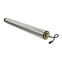
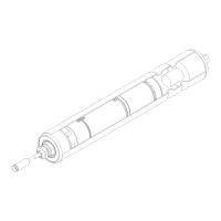
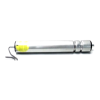
5.2 Installing the RollerDrive
Installing the attachment shaft
NOTE
Internal parts of the RollerDrive can be damaged through improper handling.
¾ Do not t the fastening nut yet
¾ Do not bend the RollerDrive cable. Allow at least 12 mm of cable to oset tensile or pressure loads.
¾ Ensure correct equipotential bonding of all metallic elements of the conveyor unit (RollerDrive, side prole,
supporting structure, etc.). Improper earthing can lead to a build-up of static charge, which can result in a
malfunction or premature failure of the RollerDrive and/or the connected control system.
¾ Remove packaging material and transport protection from the RollerDrive.
To guarantee safe equipotential bonding of the RollerDrive, the fastening nut must be in direct contact with
the metallic surface of the earthed side prole.
¾ If necessary, remove the coating of the side prole in the area of the fastening nut.
¾ Insert the RollerDrive cable and attachment shaft into the hex hole provided (min. 11.2 mm) or round hole (min.
12.2 mm) of the side prole.
¾ Position one or two round belts of 4 mm (max. 5 mm) or PolyVee belts.