Version 2.4 (03/2020) Online
Translation of the original operating manual 43 of 54
Assembly and installation
¾ Tighten the screw using a torque spanner with a tightening torque of 20 Nm.
If the parts used for attaching the RollerDrive are not the parts that have been supplied by Interroll, it is
important to ensure that the attachment is secure enough that it will not twist.
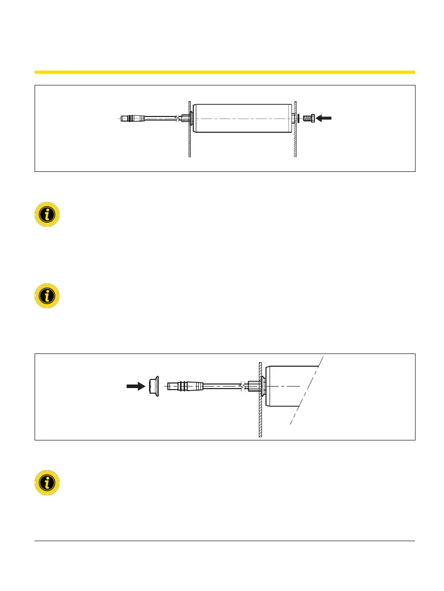
Securing the RollerDrive in the side prole
A nut is located close to the bearing housing on the attachment shaft. This inner nut is pre-tted and secured in the
correct position.
Do not twist the inner nut.
¾ Secure the inner nut with a attened counter ratchet with a 17 mm width across ats (accessory) to prevent it
from twisting.
¾ Slide the nut included in the scope of delivery over the RollerDrive line and screw it onto the attachment shaft.
¾ Tighten the nut using a torque spanner with a tightening torque of 70 Nm.
For installing a RollerDrive with tapered elements, the attachment shaft is positioned at an angle of 1.8°
or 2.2° to the side prole. To prevent bending forces from acting on the attachment shaft, an appropriate
angle compensator must be provided for the attachment. This is not included in the scope of delivery.