22 | Fieldbus Guide | Version 1.02 www.invertekdrives.com
8
Ethernet/IP Communication
8. Ethernet/IP Communication
8.1. Overview
The Ethernet/IP interface is a CIP Modbus Translator Device (CIP Type 29) providing access to a virtual Modbus device (CIP Type
28h) defined according to CIP Volume 7 specification.
8.2. Operation
COMM ERROR
P1 Ethernet P2
D1
MS
NS
D2
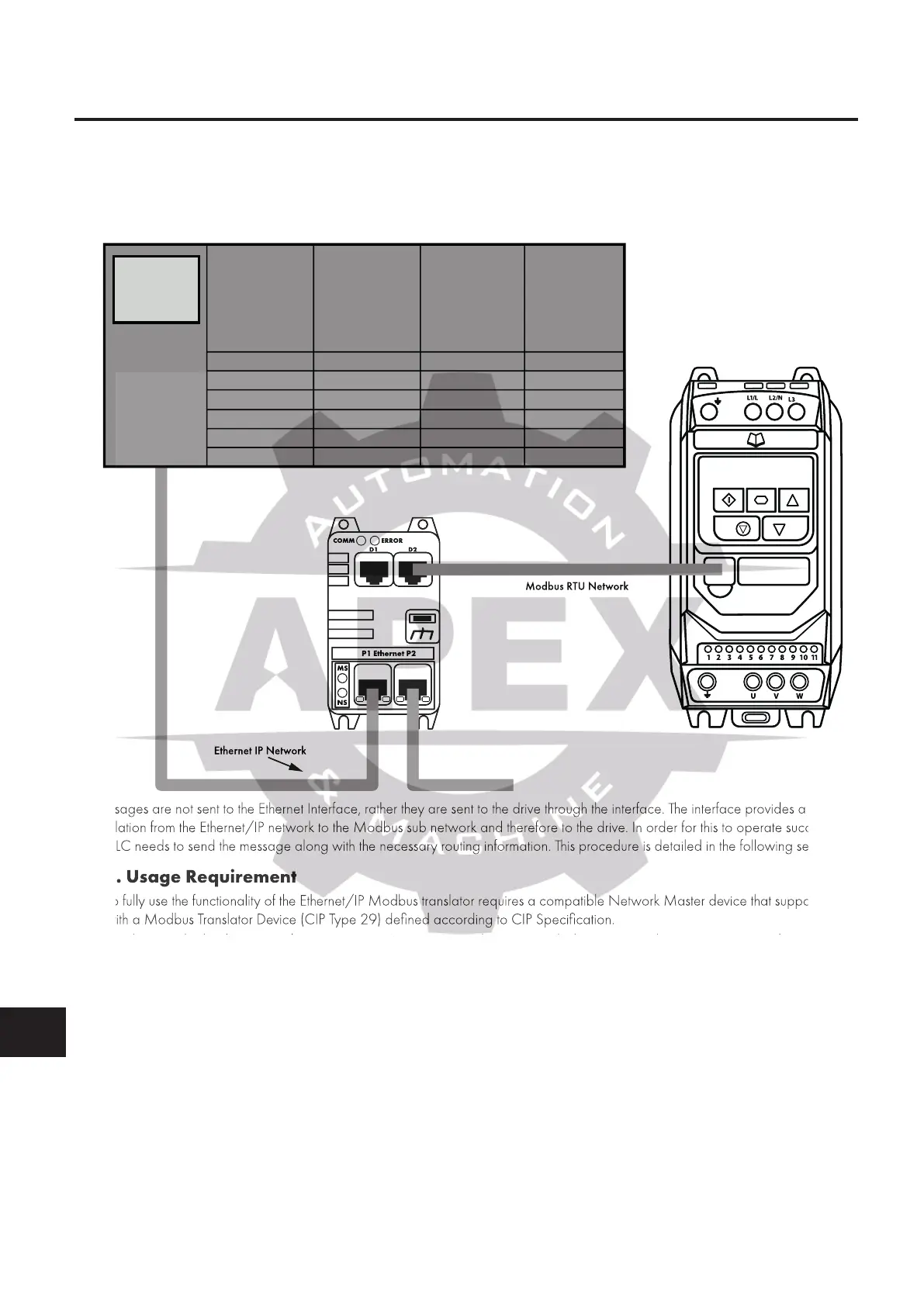
Modbus RTU Network
Ethernet IP Network
Messages are not sent to the Ethernet Interface, rather they are sent to the drive through the interface. The interface provides a
translation from the Ethernet/IP network to the Modbus sub network and therefore to the drive. In order for this to operate successfully,
the PLC needs to send the message along with the necessary routing information. This procedure is detailed in the following sections.
8.3. Usage Requirement
To fully use the functionality of the Ethernet/IP Modbus translator requires a compatible Network Master device that supports use
with a Modbus Translator Device (CIP Type 29) defined according to CIP Specification.
o Alternatively, the device may be support as a Generic CIP Bridge Device which supports cyclic communication only.
o Consult your PLC / Control Device vendor to determine compatibility.
When using the device to control the drive it is necessary to ensure that the amount of data and frequency of data exchange does
not exceed the amount of data which can be successfully exchanged on the Modbus sub-network within the permitted time.
o Recommended minimum RPI is 100ms.
o When Acyclic telegrams are exchanged, Cyclic telegrams should be paused.
Whilst the Optitools Studio PC software supports communication through the Ethernet network for device commissioning, it is not
recommended to use this continuously during operation of the drive as the additional communication load may exceed the limit
resulting in loss of Cyclic communication.
o In this case, connect the PC software to the drive serial port using the USB / RS485 adaptor.
Use port D1 or D2 of the external Ethernet adaptor.
Use port D1 or D2 of the Compact 2 Ethernet adaptor.
Use one of the available ports labelled “IOIOI”.
o Do not connect via Ethernet if data logging is required.
Messages are not sent to the Ethernet Interface, rather they are sent to the drive through the interface. The interface provides a
translation from the Ethernet/IP network to the Modbus sub network and therefore to the drive. In order for this to operate successfully,
the PLC needs to send the message along with the necessary routing information. This procedure is detailed in the following sections.
o fully use the functionality of the Ethernet/IP Modbus translator requires a compatible Network Master device that supports use
with a Modbus Translator Device (CIP Type 29) defined according to CIP Specification.
, the device may be support as a Generic CIP Bridge Device which supports cyclic communication only.

 Loading...
