56 | Fieldbus Guide | Version 1.02 www.invertekdrives.com
11
Additional Status Registers
11.3. Extended Status Registers
Modbus
RTU
Register
CAN
Open
Index
Sub
Index
PDO
Map
Parameter
Number
Upper
byte
Lower
Byte
Format Type Scaling
2001 - - - - Status Word 2 WORD R See Below
2002 - - - - Motor Output Speed S 16 R 1dp, e.g. 100 = 10.0Hz
2003 - - - - Motor Output Current U 16 R 1dp, e.g. 100 = 10.0A
2004 - - - - Motor Output Power U16 R
2dp, e.g. 100 = 1.00kW
2005 - - - - IO Status Word WORD R See Below
2006 - - - - Motor Output Torque U16 R 4096 = 100%
2007 - - - P0-08 DC Bus Voltage U 16 R 600 = 600 Volts
2008 - - - P0-09 Heatsink Temperature S16 R 50 = 50°C
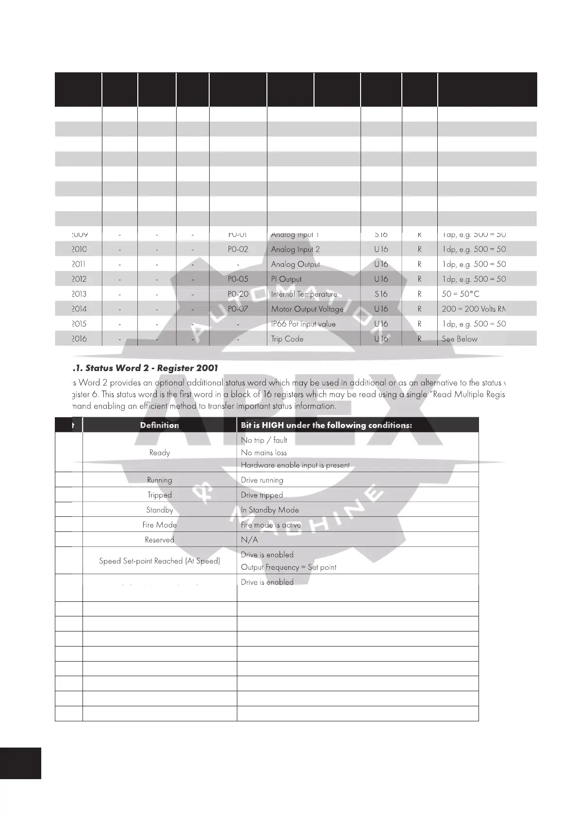
2009 - - - P0-01 Analog Input 1 S16 R 1dp, e.g. 500 = 50.0%
2 010 - - - P0-02 Analog Input 2 U16 R 1dp, e.g. 500 = 50.0%
2 011 - - - - Analog Output U 16 R 1dp, e.g. 500 = 50.0%
2 012 - - - P0-05 PI Output U16 R 1dp, e.g. 500 = 50.0%
2 013 - - - P0-20 Internal Temperature S16 R 50 = 50°C
2 014 - - - P0-07 Motor Output Voltage U16 R 200 = 200 Volts RMS
2 015 - - - - IP66 Pot Input value U16 R 1dp, e.g. 500 = 50.0%
2 016 - - - - Trip Code U16 R See Below
11.3.1. Status Word 2 - Register 2001
Status Word 2 provides an optional additional status word which may be used in additional or as an alternative to the status word
in register 6. This status word is the first word in a block of 16 registers which may be read using a single “Read Multiple Registers”
command enabling an efficient method to transfer important status information.
Bit Definition Bit is HIGH under the following conditions:
0 Ready
No trip / fault
No mains loss
Hardware enable input is present
1 Running Drive running
2 Tripped Drive tripped
3 Standby In Standby Mode
4 Fire Mode Fire mode is active
5 Reserved N/A
6 Speed Set-point Reached (At Speed)
Drive is enabled
Output Frequency = Set point
7 Below Minimum Speed
Drive is enabled
Output Frequency / Speed < P-02
8 Overload Output current > P-08
9 Mains Loss Mains power not detected
10 Heatsink > 85°C Heatsink temperature > 85°C
11 Control Board > 80°C Control PCB temperature > 80°C
12 Switching Frequency Reduction PWM switching frequency is reduced from set value
13 Reverse Rotation Motor rotates is in reverse direction
14 Reserved N/A
15 Live Toggle Bit This bit will toggle each time this register is read
2009 - - - P0-01 Analog Input 1
2009 - - - P0-01 Analog Input 1
2009 - - - P0-01 Analog Input 1
2009 - - - P0-01 Analog Input 1
2009 - - - P0-01 Analog Input 1
2009 - - - P0-01 Analog Input 1
- - - P0-02 Analog Input 2
- - - P0-02 Analog Input 2
- - - P0-02 Analog Input 2
- - - P0-02 Analog Input 2
- - - P0-02 Analog Input 2
- - - P0-20 Internal Temperature
- - - P0-20 Internal Temperature
- - - P0-20 Internal Temperature
- - - P0-20 Internal Temperature
- - - P0-20 Internal Temperature
- - - P0-07 Motor Output Voltage
- - - P0-07 Motor Output Voltage
- - - P0-07 Motor Output Voltage
- - - P0-07 Motor Output Voltage
- - - P0-07 Motor Output Voltage
- - - - IP66 Pot Input value
- - - - IP66 Pot Input value
- - - - IP66 Pot Input value
- - - - IP66 Pot Input value
- - - - IP66 Pot Input value
11.3.1. Status Word 2 - Register 2001
Status Word 2 provides an optional additional status word which may be used in additional or as an alternative to the status word
in register 6. This status word is the first word in a block of 16 registers which may be read using a single “Read Multiple Registers”
command enabling an efficient method to transfer important status information.
Bit is HIGH under the following conditions:
Hardware enable input is present
6 Speed Set-point Reached (At Speed)
6 Speed Set-point Reached (At Speed)
Output Frequency = Set point

 Loading...
