16 | Fieldbus Guide | Version 1.02 www.invertekdrives.com
6
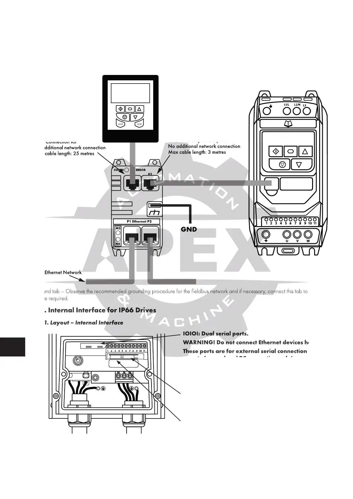
Ethernet Connection
6.2.4. Electrical Installation
WARNING! Do not connect Ethernet devices to ports D1 or D2. They may be damaged!
Power supply to the module is provided from the connected drive via the RJ45 connection.
WARNING! Do not use cross over cables! Cables must be pin to pin connected!
COMM ERROR
P1 Ethernet P2
D1
MS
NS
D2
GND
Ethernet Network
WARNING!
One Drive only on this port!
No additional network connection
Max cable length: 3 metres
ARNING!
vice only on this port!
External Keypad
Optistick Smart
PC Connection Kit
work connection
25 metres
Ground tab – Observe the recommended grounding procedure for the fieldbus network and if necessary, connect this tab to ground
where required.
6.3. Internal Interface for IP66 Drives
6.3.1. Layout – Internal Interface
L1
L3 EMCL2/N
UVW
1 2 3 4 5 6 7 8 9
10
11
I0I0I I0I0I
IOIOI: Dual serial ports.
WARNING! Do not connect Ethernet devices here!
These ports are for external serial connection of
remote keypad and PC connection only!
Port P1: Primary Ethernet port
Port P2: Secondary Ethernet Port
6.3.2. Labelling – Internal Interface
The MAC address of the device is shown below the ports.
One Drive only on this port!
No additional network connection
Max cable length: 3 metres
Ground tab – Observe the recommended grounding procedure for the fieldbus network and if necessary, connect this tab to ground
6.3. Internal Interface for IP66 Drives
6.3.1. Layout – Internal Interface
IOIOI: Dual serial ports.
! Do not connect Ethernet devices here!
These ports are for external serial connection of
remote keypad and PC connection only!

 Loading...
