Version 1.02 | Fieldbus Guide | 55www.invertekdrives.com
11
Additional Status Registers
11.1.3. PID Setpoint, Analog Output Control PDO2
This word may optionally be used for the following functions:
To set the setpoint to the PID controller
o Requires P-44 = 2
o The value range is 0 – 4096 = 0 – 100.0
o Values > 4096 are treated as 100.0%
To directly control the analog output in analog mode
o Requires P-25 = 13
o The value range is 0 – 4096 = 0 – 10Volts Output
o Values > 4096 are treated as 100.0%
11.1.4. Ramp Time PDO3
Active only when P-12 = 8 (CAN) or 4 (All other fieldbus).
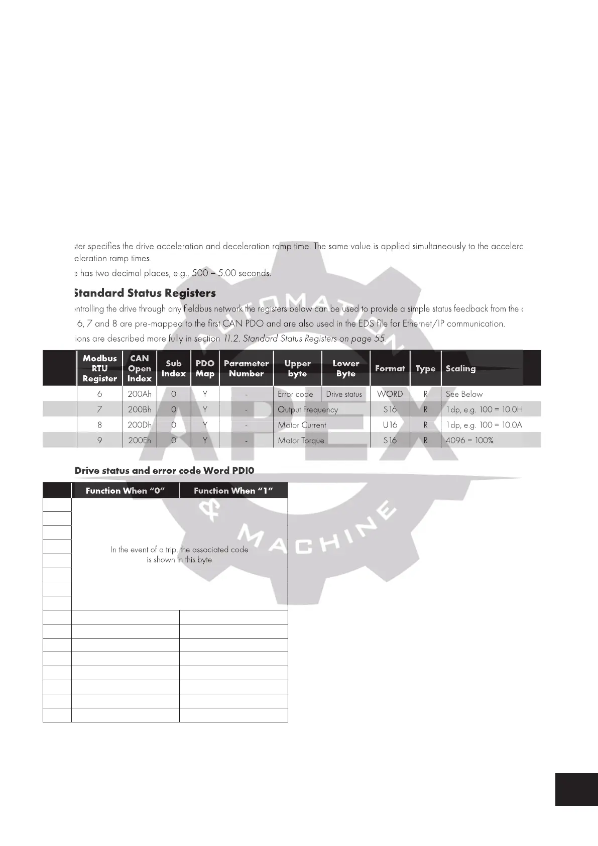
This register specifies the drive acceleration and deceleration ramp time. The same value is applied simultaneously to the acceleration
and deceleration ramp times.
The value has two decimal places, e.g., 500 = 5.00 seconds.
11.2. Standard Status Registers
When controlling the drive through any fieldbus network the registers below can be used to provide a simple status feedback from the drive.
Registers 6, 7 and 8 are pre-mapped to the first CAN PDO and are also used in the EDS file for Ethernet/IP communication.
The functions are described more fully in section 11.2. Standard Status Registers on page 55.
Name
Modbus
RTU
Register
CAN
Open
Index
Sub
Index
PDO
Map
Parameter
Number
Upper
byte
Lower
Byte
Format Type Scaling
PDI0 6 200Ah 0 Y - Error code
Drive status
WORD R See Below
PDI1 7 200Bh 0 Y - Output Frequency S 16 R 1dp, e.g. 100 = 10.0Hz
PDI2 8 200Dh 0 Y - Motor Current U 16 R 1dp, e.g. 100 = 10.0A
PDI3 9 200Eh 0 Y - Motor Torque S 16 R 4096 = 100%
11.2.1. Drive status and error code Word PDI0
Bit Function When “0” Function When “1”
15
In the event of a trip, the associated code
is shown in this byte
14
13
12
11
10
9
8
7
6 Not Ready Drive Ready
5
4
3
2 - Drive In Standby Mode
1 Drive OK Drive Tripped
0 Drive Stopped Drive Running
Bit 6: Drive Ready to Run is defined as:
Not tripped.
Hardware enable signal present (DI1 ON).
No mains loss condition.
This register specifies the drive acceleration and deceleration ramp time. The same value is applied simultaneously to the acceleration
and deceleration ramp times.
The value has two decimal places, e.g., 500 = 5.00 seconds.
11.2. Standard Status Registers
When controlling the drive through any fieldbus network the registers below can be used to provide a simple status feedback from the drive.
Registers 6, 7 and 8 are pre-mapped to the first CAN PDO and are also used in the EDS file for Ethernet/IP communication.
The functions are described more fully in section
11.2. Standard Status Registers on page 55
PDI0 6 200Ah 0 Y - Error code
PDI0 6 200Ah 0 Y - Error code
PDI0 6 200Ah 0 Y - Error code
PDI0 6 200Ah 0 Y - Error code
PDI0 6 200Ah 0 Y - Error code
PDI0 6 200Ah 0 Y - Error code
PDI0 6 200Ah 0 Y - Error code
PDI1 7 200Bh 0 Y - Output Frequency
PDI1 7 200Bh 0 Y - Output Frequency
PDI1 7 200Bh 0 Y - Output Frequency
PDI1 7 200Bh 0 Y - Output Frequency
PDI1 7 200Bh 0 Y - Output Frequency
PDI1 7 200Bh 0 Y - Output Frequency
PDI1 7 200Bh 0 Y - Output Frequency
PDI1 7 200Bh 0 Y - Output Frequency
PDI1 7 200Bh 0 Y - Output Frequency
PDI2 8 200Dh 0 Y - Motor Current
PDI2 8 200Dh 0 Y - Motor Current
PDI2 8 200Dh 0 Y - Motor Current
PDI2 8 200Dh 0 Y - Motor Current
PDI2 8 200Dh 0 Y - Motor Current
PDI2 8 200Dh 0 Y - Motor Current
PDI2 8 200Dh 0 Y - Motor Current
PDI3 9 200Eh 0 Y - Motor Torque
PDI3 9 200Eh 0 Y - Motor Torque
PDI3 9 200Eh 0 Y - Motor Torque
PDI3 9 200Eh 0 Y - Motor Torque
PDI3 9 200Eh 0 Y - Motor Torque
PDI3 9 200Eh 0 Y - Motor Torque
PDI3 9 200Eh 0 Y - Motor Torque
PDI3 9 200Eh 0 Y - Motor Torque
PDI3 9 200Eh 0 Y - Motor Torque
11.2.1. Drive status and error code Word PDI0
Bit Function When “0” Function When “1”
Bit Function When “0” Function When “1”
Bit Function When “0” Function When “1”
In the event of a trip, the associated code

 Loading...
