Version 1.02 | Fieldbus Guide | 51www.invertekdrives.com
10
Fieldbus Gateways
10.7. Profibus DP Gateway Features – OD-PROFB-IN
Complete PROFIBUS-DP slave functionality according to IEC 61158.
Supports all common baud rates up to 12 Mbit (detected automatically).
Up to 64 bytes of I/O data in each direction, allowing up to 8 Optidrives to be connected to a single gateway.
Galvanically isolated bus electronics.
10.7.1. Installation
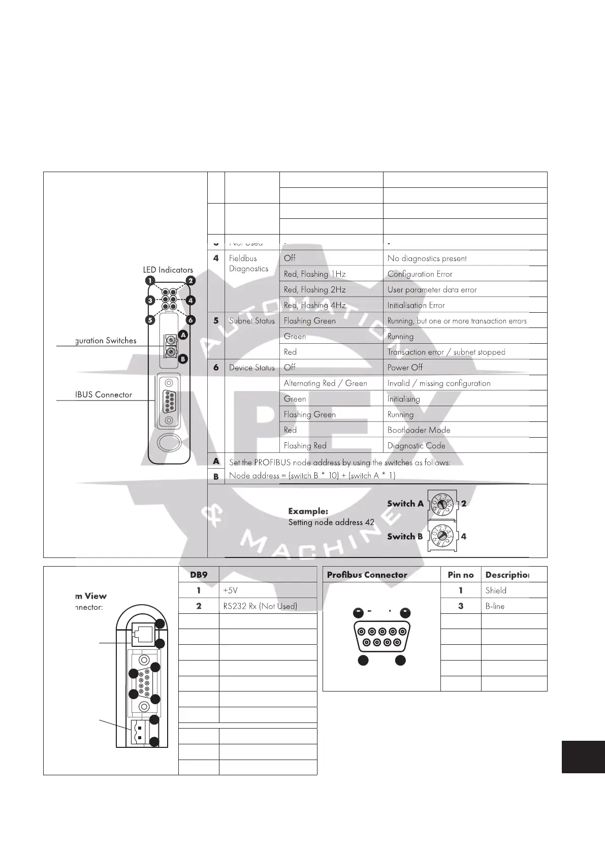
10.7.1.1. Overview - Module Front
Configuration Switches
PROFIBUS Connector
LED Indicators
1 2
3 4
5 6
A
B
1 Online Green Online
Off Not Online
2 Offline Red Offline
Off Not Offline
3 Not Used - -
4 Fieldbus
Diagnostics
Off No diagnostics present
Red, Flashing 1Hz Configuration Error
Red, Flashing 2Hz User parameter data error
Red, Flashing 4Hz Initialisation Error
5 Subnet Status Flashing Green
Running, but one or more transaction errors
Green Running
Red Transaction error / subnet stopped
6 Device Status Off Power Off
Alternating Red / Green Invalid / missing configuration
Green Initialising
Flashing Green Running
Red Bootloader Mode
Flashing Red Diagnostic Code
A
Set the PROFIBUS node address by using the switches as follows:
Node address = (switch B * 10) + (switch A * 1)
B
Example:
Setting node address 42
Switch A
Switch B
2
4
0
1
2
3
4
5
6
7
8
9
0
1
2
3
4
5
6
7
8
9
1
2
4
5
1
6
9
Bottom View
PC Connector:
1. GND
2. GND
3. RS232 Rx
4. RS232 Tx
Power:
1. +24 V DC
2. GND
1
DB9 Profibus Connector Pin no Description
1 +5V
5 Female 1
9 6
1 Shield
2 RS232 Rx (Not Used) 3 B-line
3 RS232 Tx (Not Used) 4 RTS
4 NC 5 GND bus
5 Signal 0V 6 +5V bus out
6 RS422 Rx+ (Not Used) 8 A-line
7 RS422 Rx- (Not Used) 2, 7, 9 NC
8 RS485+ Modbus RTU
9 RS485- Modbus RTU
Power
1 +24VDC, 300mA
2 0V
Red, Flashing 1Hz Configuration Error
Red, Flashing 1Hz Configuration Error
Red, Flashing 2Hz User parameter data error
Red, Flashing 2Hz User parameter data error
Red, Flashing 4Hz Initialisation Error
Red, Flashing 4Hz Initialisation Error
Subnet Status Flashing Green
Subnet Status Flashing Green
Running, but one or more transaction errors
Transaction error / subnet stopped
Alternating Red / Green Invalid / missing configuration
Alternating Red / Green Invalid / missing configuration
Set the PROFIBUS node address by using the switches as follows:
Node address = (switch B * 10) + (switch A * 1)
Profibus Connector Pin no Description
Profibus Connector Pin no Description
Profibus Connector Pin no Description

 Loading...
