6 | Fieldbus Guide | Version 1.02 www.invertekdrives.com
3
Parameter Configuration for Fieldbus Operation
3. Parameter Configuration for Fieldbus Operation
3.1. Overview
The following parameters are used to configure any fieldbus connection. Refer to the Programming Guide for further information.
Parameters are explained more fully in the Programming Guide.
3.1.1. Parameter P-12: Control Source
The fieldbus interfaces may be used to monitor information from the drive regardless of where the control commands originate.
If it is required to control the drive through the fieldbus interface, the following parameter should be adjusted as shown.
Reference: P-12 Function: Control Source Selection
Setting Function Description
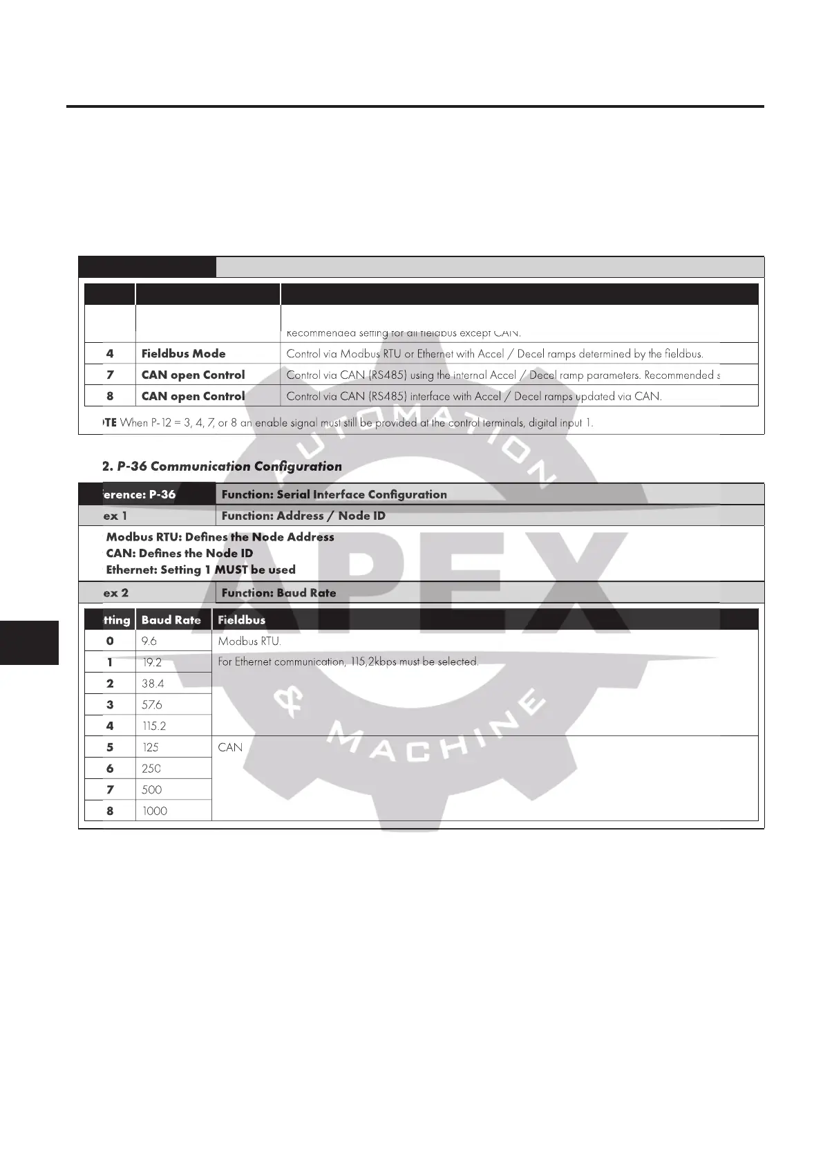
3 Fieldbus Mode
Control via Modbus RTU or Ethernet using the internal Accel / Decel ramp parameters.
Recommended setting for all fieldbus except CAN.
4 Fieldbus Mode Control via Modbus RTU or Ethernet with Accel / Decel ramps determined by the fieldbus.
7 CAN open Control Control via CAN (RS485) using the internal Accel / Decel ramp parameters. Recommended setting.
8 CAN open Control Control via CAN (RS485) interface with Accel / Decel ramps updated via CAN.
NOTE When P-12 = 3, 4, 7, or 8 an enable signal must still be provided at the control terminals, digital input 1.
3.1.2. P-36 Communication Configuration
Reference: P-36 Function: Serial Interface Configuration
Index 1 Function: Address / Node ID
For Modbus RTU: Defines the Node Address
For CAN: Defines the Node ID
For Ethernet: Setting 1 MUST be used
Index 2 Function: Baud Rate
Setting Baud Rate Fieldbus
0 9.6 Modbus RTU.
For Ethernet communication, 115,2kbps must be selected.
1 19. 2
2 38.4
3 57.6
4 115 . 2
5 125 CAN
6 250
7 500
8 1000
Recommended setting for all fieldbus except CAN.
Control via Modbus RTU or Ethernet with Accel / Decel ramps determined by the fieldbus.
Control via CAN (RS485) using the internal Accel / Decel ramp parameters. Recommended setting.
Control via CAN (RS485) interface with Accel / Decel ramps updated via CAN.
When P-12 = 3, 4, 7, or 8 an enable signal must still be provided at the control terminals, digital input 1.
3.1.2. P-36 Communication Configuration
Function: Serial Interface Configuration
Function: Address / Node ID
For Modbus RTU: Defines the Node Address
For CAN: Defines the Node ID
For Ethernet: Setting 1 MUST be used
Setting Baud Rate Fieldbus
Setting Baud Rate Fieldbus
Setting Baud Rate Fieldbus
For Ethernet communication, 115,2kbps must be selected.

 Loading...
