50 | Fieldbus Guide | Version 1.02 www.invertekdrives.com
10
Fieldbus Gateways
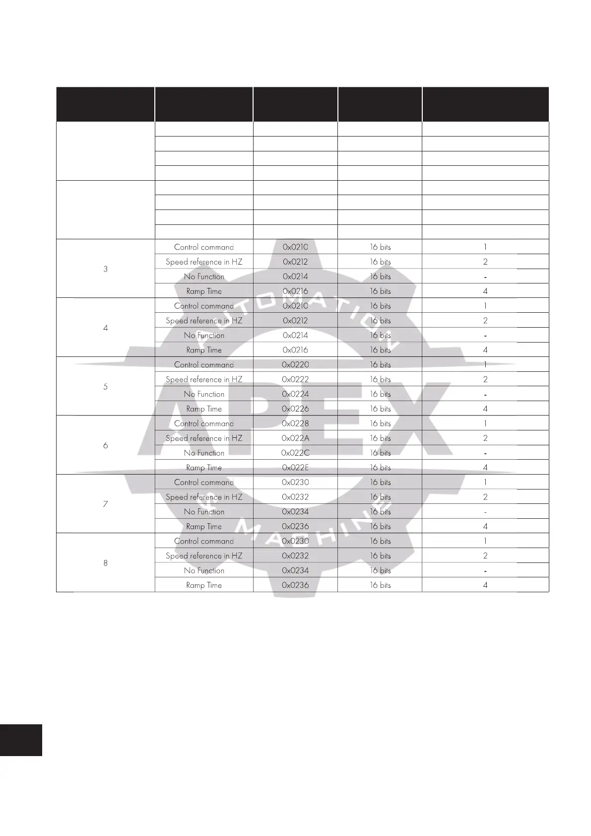
10.5.2. Output Memory
This part of the memory contains the real-time drive information that can be read by the PLC.
Drive Modbus
RTU Address
Data Start Address Data Length
Modbus Register
(Refer to section 11 for
further information)
1
Control command 0x0200 16 bits 1
Speed reference in HZ 0x0202 16 bits 2
No Function 0x0204 16 bits -
Ramp Time 0x0206 16 bits 4
2
Control command 0x0208 16 bits 1
Speed reference in HZ 0x020A 16 bits 2
No Function 0x020C 16 bits -
Ramp Time 0x020E 16 bits 4
3
Control command 0x0210 16 bits 1
Speed reference in HZ 0x0212 16 bits 2
No Function 0 x 0214 16 bits -
Ramp Time 0x0216 16 bits 4
4
Control command 0x0210 16 bits 1
Speed reference in HZ 0x0212 16 bits 2
No Function 0 x 0214 16 bits -
Ramp Time 0x0216 16 bits 4
5
Control command 0x0220 16 bits 1
Speed reference in HZ 0x0222 16 bits 2
No Function 0x0224 16 bits -
Ramp Time 0x0226 16 bits 4
6
Control command 0x0228 16 bits 1
Speed reference in HZ 0x022A 16 bits 2
No Function 0x022C 16 bits -
Ramp Time 0x022E 16 bits 4
7
Control command 0x0230 16 bits 1
Speed reference in HZ 0x0232 16 bits 2
No Function 0x0234 16 bits -
Ramp Time 0x0236 16 bits 4
8
Control command 0x0230 16 bits 1
Speed reference in HZ 0x0232 16 bits 2
No Function 0x0234 16 bits -
Ramp Time 0x0236 16 bits 4
10.6. Controlling the Optidrive(s)
The following points should be noted when attempting to control the Optidrive(s):
The drive must be set for Modbus RTU control using P-12.
Digital Input 1 which acts as a hardware enable must be ON for the drive to start, otherwise the drive will not enable, and the Sub
Network Status LED will illuminate Red when the user tries to start the drive.
The Enable / Run signal is Edge triggered, and so the drive must receive a control word with Bit 0 = 0, followed by a control word
with Bit 0 = 1 to start.
If P-12 = 3 and the user writes any data to the Ramp Time memory area, the gateway will indicate a Sub Network Status error (red
flash), as the drive rejects the data which cannot be used.
Speed reference in HZ 0x0212
Speed reference in HZ 0x0212
Speed reference in HZ 0x0212
Speed reference in HZ 0x0212
Speed reference in HZ 0x022A
Speed reference in HZ 0x022A
Speed reference in HZ 0x0232
Speed reference in HZ 0x0232
Speed reference in HZ 0x0232
Speed reference in HZ 0x0232

 Loading...
