Goodrive300-19 series open loop vector inverter special for hosit Basic operation instruction
-189-
Brake and contactor control
selection
Brake is controlled by inverter
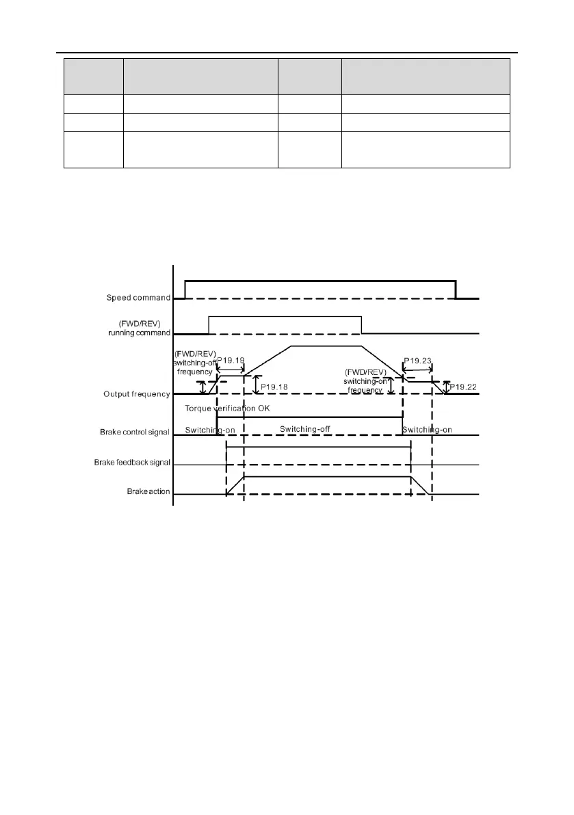
7.17 Brake control function
Accurate and reasonable sequence of brake switching on/off will avoid the hoist out of brake
effectively and ensure the safety and reliability in control. To ensure the motor opens or closes the
brake in the state in accordance with load torque, the inverter will output brake switching off according
to the internal frequency, motor current and torque. The sequence figure is as follows:
Take forward running for example:
Start: The inverter is stand-by and the brake output signal is switching-on. After receiving the running
command, the inverter will accelerate to P19.18 and simultaneously it will start torque verification.
When confirming torque verification is OK (condition: output current>=P19.13 and output
torque>=P19.14) and the output frequency>=P19.12, output brake switching-off signal and begin
switching-off delay. After P19.19, the inverter will accelerate normally and reach the set frequency.
Stop: To avoid the hoist out of brake, before switching on totally, the inverter shall have enough output
torque. After receiving the stop command, the inverter will decelerate to P19.22. When the output
frequency<=P19.20, output brake switching-on signal and begin switching-on delay. After P19.23, the
inverter will decelerate to 0 and stop.
After setting brake feedback function, if any mechanical braking fault occurs: For example, during
starting or normal running, the switching-off feedback signal is abnormal and the time exceeds
P19.24, the inverter will stop output and alarm FAE fault.

 Loading...


